
User's Manual
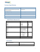
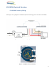
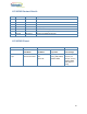
Table Of Contents

10
LCU NEMA Contact Details
LCU NEMA Pinout
#
Wire Color
Name
Purpose
1
Black
Li
AC Line In
2
White
N
AC Neutral
3
Red
Lo
AC Line Out: Load
4
Violet
Dim+
DALI(+) or (+)0-10V or PWM or RS485-A
5
Gray
Dim-
Common GND: DALI(-) or (-) 0-10V or RS485-B
6
Brown
Reserved 1
Digital IO or Analog In or RS485-A (optional)
7
Orange
Reserved 2
Digital IO or RS485-B (optional)
LED Driver
Model
Pin 1-2
Black-White
Pins 3-2
Red-White
Pins 5-4
Gray-Violet
Pins 6-7
Brown-Orange
External NEMA
7-pin
Main AC Line IN
Main AC Neutral IN
AC for lamp Line
OUT
Neutral IN
Dimming – 0-10V
Analog, DALI, PWM,
Modbus RS485
For future user
purposes, for
example, sensors,
Modbus RS485,
GPIO-digital or
analog