
Technical Specs
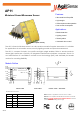
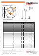
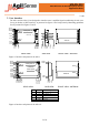
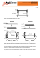
Table Of Contents

3 of 8
MSAN-010
AP11 Miniature K-Band Microwave Sensor
Application Note
V1.00
5. User Interface
The AP11 and the AP11-S are designed to interface users’ amplifier/signal conditioning circuits via a
3-way pin header or SMT interface, as presented in figures 3 and 4 respectively. Mounting guidelines
for are presented in Figures 5 and 6.
Antenna
0.00
20.10
21.50
21.15
0.35
0.70
2.78
1.40
0.00
2.52
0.55
2.25
5.06
7.60
1.40
10.14
12.68
14.00
15.20
Pin 1
Pin 5
Additional
solder pads
solder joint x2
0.00
0.24
3.54
0.00
1.30
13.90
15.20
Pin 1
Pin 5
Y
X
SIDE VIEW FRONT VIEW - ANTENNA
REAR VIEW
Pin
Name
Description
1
GND
Ground
2
+V
3 V Supply, V
in
3
IF
IF
out
4
GND
Ground
5
GND
Ground
Figure 4. Interface and pinout of the AP11-S.
Antenna
SIDE VIEW
FRONT VIEW - ANTENNA
REAR VIEW
0.00
1.25
2.65
21.35
22.75
24.00
0.00
1.40
2.52
5.06
10.14
7.60
12.68
14.00
15.20
2.94
3.18
6.48
Pin 1
Pin 5
Y
X
solder joint 2
0.00
11.76
5.67
Ø1.0
8
Figure 3. Interface and pinout of the AP11.