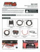
RG4-5KRC Polaris Ranger with Ride Command Kicker 5-Speaker Audio Kit SSV WORKS, 201 N. Rice Ave Unit A, Oxnard, CA 93030 www.SSVworks.com I Phone: 818-991-1778 I Fax: 866-293-6751 WARRANTY INFORMATION: All SSV Works enclosures are covered by a limited lifetime warranty against defects in material or workmanship. All SSV Works Electronics are covered by a limited 1 year warranty against defects in material or workmanship.
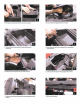
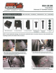
C. With push pins extracted, lift to remove the cup holder. D. Lift and disconnect gauge cluster for removal. E. Unscrew (4) torx screws located in upper glove box and remove box. F. Extract push pins that are now exposed from removing the upper glove box. G. Extract push pins exposed from cup holder removal. H. Extract push pins exposed from gauge cluster removal. I. Extract push pins located above driver and passenger side cup holders. J. Lift to remove the dash.
K. Extract push pins located beneath 12v sockets. M. Unscrew (2) torx screws that were behind the front dash panel. L. Remove front dash panel and disconnect the 12v socket harness. N. Unscrew the two (2) torx screws connecting the dash bracket at the rear of the dash cavity. Remove the under dash bracket. NOTE: IT WILL NOT BE RE-INSTALLED. MRB3/ AMP MOUNTING PLATE AND DASH CONTROLLER INSTALLATION 0. Move the factory wiring to the rear of the dash cavity.
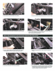
S. With the cables now through the firewall, route them down the front of the machine to be full through the into the cabin of the machine. NOTE: A 1" hole may need to be drilled to run the cables down the front of the chassis. T. Follow the air ducts and factory wiring and feed cables towards the battery compartment. (use provided zip ties to secure cables to factory wiring, away from the drive shaft). U.
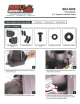
RG4-US10K Polaris Ranger Underseat 10" Subwoofer Enclosure SSV WORKS, 201 N. Rice Ave Unit A, Oxnard, CA 93030 www.SSVworks.com I Phone: 818-991-1778 I Fax: 866-293-6751 TOOLS NEEDED FOR INSTALLATION - T-30 & T-40 Torx Driver - 4mm Allen Key - Panel Removal Tool - Drill -13/64" Drill Bit PARTS LIST IMAGES 1. RG4-US10 Enclosures 2. Enclosure Bracket A 2. Enclosure Bracket B 4. M6 Flathead 4mm 5. M6 Allen Torx Hex Screws x4 Screws x2 •• •• 5.
E. Place SSV bracket B over the factory screw holes and refasten down with the (3) factory T40 torx screws removed in the previous step. G. With the brackets seated into one another, use the front mounting tabs as a template to mark with a scribe or punch the needed placement to drill pilot holes. F. With the bracket secured to the floorboard, place the enclosure in front of the floorboard bracket.
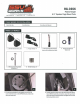
RG4-F65K Polaris Ranger 6.5" Speaker Front Kick Panels SSV WORKS, 201 N. Rice Ave Unit A, Oxnard, CA 93030 www.SSVworks.com I Phone: 818-991-1778 I Fax: 866-293-6751 TOOLS NEEDED FOR INSTALLATION - T-30 Tonc Driver - Panel Removal Tool - Phillips Screwdriver PARTS LIST IMAGES . .' - ,, -· ·.,, ~ 0 . ~· ' 1. RG4-F65 Enclosures (1 pair) 2. Enclosure Brackets x 4 3. M6 x 16mm Screws X 10 4. M6 Washers x 8 (small) 4. M6 Washers x 2 (large) II A.
II E. Place the speaker pod in location and resecure the factory screws through the pod brackets on the front and underneath the dash. P. From the inside-top of the dash, secure the top mounting MG screw and large washer to the pod through the smaller hole next to the routed speaker wire (figure Fl). Then connect the B-H 1149 harness to the speaker cable coming out of the speaker pods (figure P2). G. Connect the dash end of the B-H 1151 harness to the amp.
RG-C65K Polaris Ranger 6.5" Speaker Cage Mount Pods SSV WORKS, 201 N. Rice Ave Unit A, Oxnard, CA 93030 www.SSVworks.com I Phone: 818-991-1778 I Fax: 866-293-6751 - 5mm Allen Key - 3mm Allen Key - 8mm Open End Wrench PARTS LIST IMAGES 0 1. US2-C65 Enclosures (1 pair, 2. R~nger Clamp x 4 3. Aftermarket Speaker Adapter (comes with unloaded pods only) 4. MG Hex Head Bolts & Washersx4 0 5. MG Allen Socket Head Bolts & Washersx4 6. MG Set Screws x 8 A.
C. Position the clamp underneath the rear crossbar D. Slide the top mount for the clamp into the top crossbar notch and line up screw holes. E. Place screws in the clamp and use a 5mm hex driver to tighten the bracket F. Route the speaker wire away from any moving parts and any sharp metal, then connect to the amplifier.
CONNECTING POWER H. Feed the power and ground wires from the B-H1221 (MRB3 brain power) and the USB/AUX port through the grommet that passes through the firewall from under the dash to under the hood. B. From the B-HPGAT Harness: use accessory red wire for power to USB/Auxadapter, use yellow wire for power to B-H1221 from the MRB3 bra in, both grounds from USB/Aux adapter and B-H 1221 crimp to black wire. C. Connect the HPGAT harness to an empty port on the factory buss bar located under the hood.
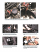
CONNECTING POWER & GROUND CABLE TO BATTERY Power Wire Battery Terminal Cable ... Break off tab Al. Remove the bottom cover of the fuse holder by extracting the 2 screws. Break off the right and left side tabs on the bottom cover. A2. Extract both fuse holder screws. II A3. Attach both the Power Wire and Battery Terminal Cable to the fuse holder. Reattach the bottom cover. ■ B. Unscrew the factory nut on the negative battery terminal.