Series D Ductile Iron Positive Displacement Rotary Lobe Pumps Operating Manual M/103/0301
Operating Manual Alfa Laval Pumps Ltd Birch Road, Eastbourne, East Sussex BN23 6PQ Tel No : (01323) 412555 Fax (01323) 412515 EC DECLARATION OF INCORPORATION We hereby declare that the following machinery is intended for installation into a machine or to be assembled with other machines into a machine.
Operating Manual
Operating Manual Alfa Laval Pumps Ltd Birch Road, Eastbourne, East Sussex BN23 6PQ Tel No : (01323) 412555 Fax (01323) 412515 EC DECLARATION OF CONFORMITY We hereby declare that the following machinery conforms to the machinery directive 89/392/ EEC as amended by 91/368/EEC, 93/44/EEC and 93/68/EEC and to the following other relevant directives.
Operating Manual
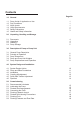
Operating Manual Contents 1.0 General 1.1 1.2 1.3 1.4 1.5 1.6 Pump Limits of Application or Use Duty Conditions Noise Levels Utility Requirements Safety Precautions Health and Safety Information Page No 1 1 1 1 2 3 2.0 Unpacking, Handling and Storage 2.1 2.2 2.3 2.4 Documents Unpacking Handling Pump Storage 4 4 4 5 3.0 Description of Pump or Pump Unit 3.1 3.2 3.3 3.4 3.
Operating Manual Contents Page No 6.0 Start up, Shut Down and Cleaning in Place 6.1 Start up Checklist 6.2 Pump Shut Down Procedure 6.3 Direction of Rotation 19 20 20 7.0 Maintenance and Inspection 7.1 Maintenance Schedule 7.2 Recommended Spare Parts 7.3 Maintenance Tools 21 21 22 8.0 Rotor Retention 8.1 Torque Locking Assembly - Mounting Instructions 8.2 Torque Locking Assembly - Release Instructions 8.3 Rotor Retention - Torque Locking Assembly 23 23 24 9.0 General Maintenance 9.1 9.2 9.3 9.4 9.
Operating Manual Contents Page No 11.0 Product Seal, Removals and Fittings 11.1 11.2 11.3 11.4 11.5 14.6 Single Mechanical Seal Single Flushed Mechanical Seal Double Mechanical Seal Packed Gland Packed Gland with Flush Mechanical Sewage Seal 12.0 Faults, Causes and Remedies 36 37 38 39 40 41 42 13.0 Technical Data 13.1 13.2 13.3 Pump Information Chart Seal Specification Chart Torque Specification Chart 43 43 44 14.0 Exploded Drawings and Parts List 14.1 14.2 14.1 14.
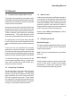
Operating Manual 1.0 General 1.1 Pump Limits of Application or Use This range of pumps has been designed to offer a wide span of transfer duties throughout industry where the use of stainless steel for pumphead components is not essential. Pressures of up to 15 bar, speeds to750rpm and temperatures to 200°C can be obtained on this range of pumps depending on pump model/size. These conditions cannot always be obtained simultaneously. The model type/size will be shown on the nameplate positioned on the pump.
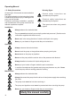
Operating Manual 1.5 Safety Precautions All warnings in this manual are summarised on this page. Pay special attention to the instructions below so that severe personal injury or damage to the pump can be avoided. Personnel performing installation, operation and maintenance of the pump must have the relevant experience required. Installation Warning Signs : General safety instructions are preceded by this symbol. Electrical safety instructions are preceded by this symbol.
Operating Manual 1.6 Health and Safety Information General First Aid Potential Safety Hazards If potentially hazardous substances are accidentally inhaled, or skin or eyes contaminated, then the following basic precautions should be taken The following section gives information on handling, storage and disposal of parts and materials used in the pumps which may be considered hazardous to health.
Operating Manual 2.0 Unpacking, Handling and Storage To avoid any problems, on receipt of your pump always use the following procedure:2.1 Documents 1. Check the delivery note against the goods received. 2. If the pump has been delivered with an electric motor check that the motor instructions are available. 2.2 Unpacking Care must be taken when unpacking the pump, and the following stages must be completed:1. Inspect the packing for any possible signs of damage in transit. 2.
Operating Manual 2.4 Pump Storage After receipt and inspection if the pump is not to be installed immediately the pump should be repacked and placed in suitable storage. The following points should be noted:1. Plastic or gasket type port covers should be left in place. 2. Pumps received wrapped with corrosion inhibiting treatment material should be rewrapped. 3. A clean, dry, vibration free location should be selected.
Operating Manual 3.0 Description of Pump or Pump Unit 3.1 General Pump Description The pump supplied is a positive displacement pump, which may be supplied with or without a drive unit (see below). The drawing below indicates various parts of the pump. Rotorcase Pump Drive Unit Drive Shaft Front Cover Coupling Guard (Houses Coupling) Ports Pump with Drive Unit Product Seal Area Bareshaft Pump Gearbox 3.2 Principle of Operation The rotors are timed such that when they rotate no contact occurs.
Operating Manual 3.3 Pump Dimensions L 'A' Port Size Shaft Dis G F J KW Key Width B KS Key & Shaft Dia B D HT C HB T Q E R 4 Holes'U' Ø S N P M All dimensions in mm PUMP MODEL D4-0095 A B C D E F G HB HT J KS KW L M N P Q R S T U 75 170 520* 100 170 530* 163 307 20 38 80 115 211 63 41 338* 163 307 20 38 80 115 211 63 41 338* D5-0290 100 190 550* 100 190 550* 150 190 195 371 20 45 110 135 255 70 48.
Operating Manual 3.4 Pump and Pump Unit Weights Pump Unit - Pump complete with Drive Unit Bareshaft Pump Pump Model Bareshaft Pump KG Pump with Drive Unit KG D4-0079 D4-0095 D4-0140 110 113 130 147 150 220 D5-0168 D5-0200 D5-0290 170 176 192 264 270 350 D6-0353 D6-0420 D6-0600 281 289 300 392 400 530 The above weights are for guidance only and will vary depending upon the specification of the pump, baseplate and drive unit.
Operating Manual 3.5 Pump Displacement and Capacities The following table details the pump capacities for the pump models. This figure will change depending upon speed, pressure, temperature and product being pumped. Pump Ref Displacement litres/rev Maximum Speed Water (rpm) Maximum Capacity at Maximum Speed m³/hr D4-0079 D4-0095 D4-0140 0.79 0.95 1.40 750 500 500 35.6 28.5 42.0 D5-0168 D5-0200 D5-0290 1.68 2.00 2.90 600 500 500 60.5 60.0 87.0 D6-0353 D6-0420 D6-0600 3.53 4.20 6.
Operating Manual 4.0 System Design and Installation 4.1 System Design Advice When designing the pumping system :Do Do - - confirm with the supplier the Net Positive Suction Head (NPSH) requirements for the pump, as this is crucial for ensuring the smooth operation of the pump and preventing cavitation. avoid suction lifts and manifold/ common suction lines for two pumps running in parallel, as this may cause vibration or cavitation.
Operating Manual 4.2 Pump and Base Foundations 4.3 Installation Depending on your requirements the pump and drive (if supplied) may arrive mounted on a baseplate. Our standard baseplates have pre-drilled fixing holes to accept base retaining bolts. Before the pump is installed it is advisable to consider the following: Always - Ensure that the mounting surface is flat to avoid distortion of the baseplate. This will cause pump/motor shaft misalignment and pump/motor unit damage.
Operating Manual 4.4 Coupling Misalignment Parallel Misalignment When installing the pump and drive unit, it is essential to ensure that the coupling is not twisted during installation. The main cause of misalignment is by fitting the baseplate to an uneven surface. Angular Misalignment Check the maximum angular and parallel allowable misalignments for the couplings before operating the pump. Coupling Type Recommended Maximum Parallel Misalignment Size 1 mm Maximum Angular Misalignment Degrees 0.
Operating Manual 4.5 Pulley Belt Tension Adjustment An incorrectly tensioned belt will cause belt slip and short belt life. An excessively tensioned belt will overload both belts and bearings. Always use a belt tension gauge fo setting up. 1. Measure the span length. 2. Calculate the required deflection: ('x') Span Isolate the drive unit and pump from all power and control supplies before attempting to work on adjusting the belts.
Operating Manual 4.6 Pipework All pipework must be supported. The pump must not be allowed to support any of the pipework weight. Remember - Pipework supports must also support the weight of the product being pumped. Keep - Pipework horizontal where applicable to reduce air locks. Include eccentric reducers on suction lines. Check - Coupling alignment during installation to highlight pipework alignment/support problems. Install - A liquid trap around to pump to assist in priming.
Operating Manual 5.0 Commissioning 5.1 Recommended Lubricants 5.2 Lubricating the Pump Pumps specified oil filled :- Changing the Oil :- The pump will not be supplied with oil therefore the table below must be used to select a recommended oil. First change - After 150 hours of operation. Next change - Every 3000 hours of operation.
Operating Manual 5.3 Flushed Seal Arrangements 5.4 Connecting the Flush5 A flushed seal arrangement is fitted in order to cool the seal area. The following equipment is strongly recommended when using a flushing system. It is important that:- - Control valve and pressure gauge, to enable the correct flushing pressure to be obtained and monitored. (A constant flow valve can be used).
Operating Manual 5.5 Flushing Pipework Layout This suggested arrangement is for single mechnical seals. If the pump is fitted with double mechanical seals or packed glands the pressure gauges and control valves should be fitted on the outlet side of the system. E Note :- The pipework and fittings are not supplied with pump.
Operating Manual 5.6 Flushed Seal Housing Connections Pump Model Single/Double Mech. Seal Packed Gland D4 1/8” 1/4” D5 1/8” 1/4” D6 1/8” 1/4” All connections BSPT or NPT as specified at the time of order. 5.7 Flushing Fluid 5.8 Flushing Pressure and Flow Rate The choice of flushing fluid is dependant upon the pumping media and duty conditions i.e. pressure and temperature. Usually water is used for cooling or flushing water soluble products.
Operating Manual 6.0 Start up, Shut Down and Cleaning in Place 6.1 Pump Start-up Checklist 1. Is the location of the 'stop' button clear? 2. Has the pipework system been flushed through to purge welding slag and any other hard solids? 3. Have all obstructions been removed from the pipework or pump? 4. Are the pump connections and pipework joints tight and leak-free? 5. Is there lubrication in the pump and drive unit? 6.
Operating Manual 6.2 Pump Shut Down Procedure 1. Turn the pump off. 2. Isolate the pump/drive unit from all power and control supplies. 3. Close the pipework valves to isolate the pump. 4. If the pump is to be dismantled refer to the dismantling section. 6.3 Direction of Rotation The direction of flow is dictated by the direction of rotation of the drive shaft. Reversing the direction of rotation will reverse the flow direction.
Operating Manual 7.0 Maintenance and Inspection 7.1 Maintenance and Schedule 7.2 Recommended Spare Parts It is advisable to install pressure gauges either side of pump so that any problems within the pump/pipework will be highlighted. The following table details the recommended spare parts which should be retained within your maintenance stock.
Operating Manual 7.
Operating Manual 8.0 Disassembly Rotor retention on all pumps in the DRM range is by Torque Locking Assembly (TLA) with flush fitting rotor caps. The rotor spline area is sealed with three O'rings per rotor (A, B, & C), one (A) between the shaft and rotor, and two (B & C) seated in the rotor cap. The rotor caps are retained by socket head cap screws. The TLA's should be tightened to the recommended torque values. 'O' Ring 'C' 'O' Ring 'B' TLA 3.
Operating Manual 8.3 Rotor Retention: Torque Locking Assembly Rotor Clamp TLA Rotor Screw Access to TLA through slots Torque Values for Rotor Torque Locking Assemblies 25 Pump Torque Nm (lbft) Key Size mm D4 4.1 (3.0) 3 D5 8.5 (6.3) 4 D6 14.0 (10.
Operating Manual 9.0 General Maintenance 9.1 Before Dismantling the Pump Before starting to dismantle the pump Always:Purge the pump and system if any noxious products have been pumped. Isolate pump/drive unit from all power and control supplies. Close pipework valves to isolate the pump Disconnect the pump from the drive unit.
Operating Manual 9.2 Removing the Rotors 1. Before starting to dismantle the pumphead isolate the driver/pump from all power and control supplies, purge the system if any noxious products have been pumped. Read the safety section carefully. 2. Ensure isolating valves to the pump are closed. 3. Carefully loosen the front cover retaining screws, there may still be residual pressure in the system. 4. Remove the front cover retaining screws and take off the cover.
Operating Manual 9.3 Removing the Rotorcase 1. Before proceeding disconnect the suction and discharge piping. 2. Remove the rotors as described previously. On pumps D5 and D6 shut the hinged front cover (where fitted) and loosely fasten with front cover screws. 3. 5. Between the rotorcase and gearcase, preshaped plastic shims are used to adjust the rotor clearances. These must be replaced exactly as removed, otherwise excessive wear or damage may occur to the rotors and/or rotorcase. 6.
Operating Manual 9.4 Replacing the Front Gearcase Seals 1. Follow the procedure for the removal of rotors and rotorcase. 2. Remove the product seal. 3. Three socket head screws retain the seal carrier, once removed the carrier can be extracted. As silicon sealant or a gasket is used to seal the faces the carrier may have to be eased off carefully with a lever. 4. Once the carriers are removed from the pump the seals can be pressed out and replacements pressed in using a suitable dolly. 5. 6.
Operating Manual 9.5 Fitting and Shimming the Rotorcase 9.6 Front Cover Reversal When fitting a rotorcase correct shimming is critical. Shims are fitted between the rotorcase and gearcase and are used to control the back clearances between the rotor and rotorcase. Plastic colour coded shims are used on all series D pumps. If the pump has previously been shimmed, the old shims may be reused provided they are replaced in their original positions.
Operating Manual gearbox dismantled the pump will have to be retimed as described in the timing adjustment section. 9.7 Removal of Rear Gearcase Cover and Replacement of Seal 1. 2. 3. Isolate the motor, remove any coupling or Vee belt guards. If the pump is direct coupled it will be necessary to disconnect the coupling and remove the pump from the baseplate before removing the gearcase cover. Drain the oil from the pump. 5.
Operating Manual 9.9 Wearplates Replacing Wearplates 1. Before fitting new wearplates thoroughly clean the inside of the rotorcase where the wearplates will be sealed. In addition wipe clean the rear face of the new wearplates. 2. The new wearplates will be supplied with the studs already attached. 3. Just prior to fitting the wearplates apply silicon sealant, or similar, to the wearplate studs. 4.
Operating Manual 10.0 Gearbox Components 10.1 Timing Gears Each pump is fitted with a pair of timing gears, which are located in the rear of the gearcase and ensure synchronisation of the rotors, such that under normal working conditions they will not contact one another. The timing gears on pumps in the D range are retained using Torque Locking Assemblies (TLA) similar to those used to retain the rotors. The method of correctly tightening the TLA's is the same as for the rotors as previously described.
Operating Manual 10.2 Timing Adjustment The rotor timing (synchronisation) is set-up in the factory. If the rotors become unsynchronised, they may be retimed using the following procedure. To remove the timing gears the following procedure is recommended. 1. Drain lubricant. 2. Remove rear gearcase cover. 3. Release torque locking assemblies. (refer to page 23 - 8.2) To adjust the timing of the rotors, first remove the gearcase end cover, once the cover is removed the timing gears will be exposed.
Operating Manual 10.6 Shaft Removal 1. Remove rotorcase front cover, rotor and rotorcase. 3. Locate outer shell of bearing onto the cone just fitted. 2. Remove product seals. 4. Locate bearing spacer onto shell just fitted. 3. Remove the gearcase rear cover, timing gears and drain lubricant. 5. Locate rear bearing shell, of front set of bearings, onto the spacer. 4. Remove the gearcase front seal retainers and seals. 6. 5.
Operating Manual 10.10 Shaft Replacement Gearboxes are assembled with the top shaft bearing located against a machined surface in the bearing housing, and the bottom shaft bearings butting against a spacer fitted into the front bearing housing. When a new gearbox is being built this spacer is initially oversized, such that the axial displacement in the rotor abutment shoulders can be measured and the appropriate spacer fitted, or the existing spacer ground to suit.
Operating Manual 11.0 Product Seals Removal and Fitting 11.1 Single Mechanical Seal Item 1 2 3 4 5 6 Description Shaft Abutment Spacer Stationary Face 'O' Ring Stationary Face Rotary Face Shaft 'O' Ring Wave Spring Drive Ring Fitting the Single Mechanical Seal The seal comprises of a rotary face which is sealed to the shaft by an 'O' ring. A wave spring(s) provide a force to maintain face to face contact. Rotation is provided by socket set screws which are tightened onto the shaft.
Operating Manual 11.2 Single Mechanical Seal Item 1 2 3 4 5 6 7 8 9 10 11 Description Stationary Face 'O' Ring Stationary Face Rotary Face Shaft 'O' Ring Wave Spring Drive Ring Spacer O' Ring Spacer Gasket Seal Housing Lip Seal The seal comprises of a rotary face which is sealed to the shaft by an 'O' ring. A wave spring(s) provide a force to maintain face to face contact. Rotation is provided by socket set screws which are tightened onto the shaft.
Operating Manual 11.3 Double Mechanical Seal Item 1 2 3 4 5 6 7 8 9 10 11 12 13 Description Stationary Face 'O' Ring Stationay Face Rotary Face Shaft 'O' Ring Wave Spring Dive Ring Wave Spring Shaft 'O' Ring Rotary Face Stationary Face Gasket Stationary Face 'O' Ring Seal Housing Rotorcase Side Note:- The drive ring chamfer must be on the gearcase side of the shaft. The seal consists of two rotary faces which are sealed to the shaft by 'O' rings.
Operating Manual 11.4 Packed Gland Arrangements Packed Gland Item 1 2 3 4 Description Item 5 6 7 8 Shaft Sleeve O' Ring Shaft Sleeve Spacer Packing Rings Drip leakage is essential to prevent overheating of the gland area which will cause seal failure. Fitting the Packed Gland Lubricate the 'O' ring, locate in shaft sleeve and slide onto the shaft. 2. Tighten up the socket set screws, ensuring tha the drilled dimples are aligned with the grub screws.
Operating Manual 11.5 Packed Gland Adjustment Packed Gland with Flush Item 1 2 3 4 5 6 7 8 9 Shaft Sleeve 'O' Ring Shaft Sleeve Spacer Packing Rings Lantern Ring Adjusting the Packed Gland Drip leakage is essential to prevent overheating of the gland area which will cause seal failure. Important : Stop and remove gland guard for checking temperature of housing and observing leakage. Always replace the guard before re-starting. 1. Lightly tighten up the gland follower. 2.
Operating Manual 11.6 Mechanical Sewage Seal Item 1 2 3 4 5 6 7 8 9 10 11 12 Description Bronze Bush Gasket Socket Set Screw Wave Spring 'O' Ring Shaft Seal Housing Shaft Rotorcase Rotary Assembly Rotary Face Stationary Face 'O' Ring Housing The Sewage Seal comprises of an internally mounted single mechanical seal, bronze bush and seal housing. The single mechanical seal has a rotary face which is sealed to the shaft by an 'O' ring. A wave spring provides a force to maintain face to face contact.
DIAGNOSIS WILL BE GREATLY ASSISTED BY TAKING ON-STREAM PRESSURE READINGS AT THE PUMPS INLET AND OUTLET PORTS Operating Manual 12.
Operating Manual 13.0 Technical Data 13.1 Pump Information Chart D4-0095 Suction & Discharge Connections Connection Size international stds Displacement Pump Model Litres/ I gal/ US gal/ rev. 100 rev. 100 rev. 0.95 20.9 25.0 Differential Pressure Max Speed (Sludge) Max Speed (Water) Max Capacity (Water) mm 75 inches 3 bar 5.0 lbf/in 72 rev/min 350 rev/min 500 m³/h 28.5 l/sec 7.9 D4-0140 1.40 30.8 36.8 100 4 5.0 72 350 500 42.0 11.6 D5-0200 2.00 44.0 52.6 100 4 5.
Operating Manual 13.3 Torque Specification Chart Pump Model Rotor TLAs Front Cover Screws Torque Spanner Size Torque Gearcase Nuts Key Size Torque Timing Gears TLAs Spanner Size Torque Key Size D4 Nm 39 lbft 29 mm 17 Nm 4.1 lbft 3 mm 3 Nm 64 lbft 47 mm 19 Nm 14 lbft 10 mm 5 D5 39 29 17 8.5 6.3 4 64 47 19 35 26 6 D6 64 47 17 14 10.3 5 175 129 24 35 26 6 Front Seal Carriers and Rear Covers Torque 25 Nm (19 lbft) - Key Size 6mm Wearplates Torque 8 Nm (5.
Operating Manual 14.0 Exploded Pump Drawing and Parts List 14.
Operating Manual Exploded Pump Drawing and Parts List 14.
Operating Manual 46
Operating Manual Exploded Pump Drawing and Parts List 14.
Operating Manual 47
Operating Manual Exploded Pump Drawing and Parts List 14.
Operating Manual 48