MODEL SR560 LOW-NOISE PREAMPLIFIER 1290-D Reamwood Avenue Sunnyvale, CA 94089 U.S.A. (408) 744-9040 Copyright © 1989, 1990, 1997, 1999 Stanford Research Systems All Rights Reserved. Revision 2.
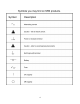
TABLE OF CONTENTS Introduction and Setup Instrument Overview Preparation for Use Line Voltage Line Fuse Line Cord Ventilation Power-Up Repackaging for Shipment Use in Biomedical Applications Warning Regarding Use with Photomultipliers Accessories Furnished Environmental Conditions Symbols 1 2 2 2 2 2 2 3 3 3 3 3 4 Specifications SR560 Low Noise Preamplifier Specifications Chart 5 Operation and Controls Front Panel Operating Summary Power Source Filters Gain Mode Gain Output Reset Status Rear Panel Opera
TABLE OF CONTENTS Calibration and Repair Offset Adjustment Calibration Front End Replacement SR560 Offset Adjustment Procedure Battery Replacement Fuse Replacement Noise Contours Input Voltage Noise Dynamic Reserve 17 17 17 18 18 18 19 20 20 Appendix A Remote Programming Introduction Commands A-1 A-1 A-1 Appendix B Noise Sources and Cures Intrinsic Noise Sources Johnson Noise '1/f' Noise Others Non-Essential Noise Sources Capacitive Coupling Inductive Coupling Resistive Coupling ('Ground Loops') Microph
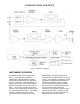
INTRODUCTION AND SETUP Figure 1: SR560 Block Diagram INSTRUMENT OVERVIEW BNC amplifier" with the amplifier ground isolated from the chassis and the AC power supply. Opto-isolated input blanking control and listen-only RS-232 interface lines are provided for instrument control. Digital noise is eliminated by shutting down the microprocessor's oscillator except during the short time required to alter the instrument's configuration, either through a front-panel pushbutton or through an RS232 command.
INTRODUCTION AND SETUP independent operation. Rear panel banana jacks provide access to the internal regulated power supplies (or batteries) for use as a bias source. Line Fuse Verify that the correct line fuse is installed before connecting the line cord to the unit. For 100 V and 120 V, use a 1 Amp fuse and for 220 V and 240 V, use a 1/2 Amp fuse.
INTRODUCTION AND SETUP ROLLOFF HIGH-PASS LOW-PASS GAIN MODE GAIN LISTEN DEVICE ADDRESS bypassed 0.03 Hz, +6 dB/oct 1 MHz, -6 dB/oct High Dynamic Reserve 20, calibrated ON As per SW601 Accessories Furnished - Power cable - Operating Manual Environmental Conditions OPERATING Temperature: 10°C to 40°C Relative Humidity: <90% Non-condensing Repackaging for Shipment The original packing materials should be saved for reshipment of the SR560.
4
SPECIFICATIONS SR560 LOW-NOISE PREAMPLIFIER SPECIFICATIONS CHART Inputs Single-ended or true differential Impedance 100 MΩ + 25 pF, DC-coupled Maximum Inputs 1 VDC before overload; 3 V peak to peak max AC coupled; protected to 100 VDC Maximum Output 10 Vpp Noise <4 nV/√Hz at 1 kHz CMRR >90 dB to 1 kHz, decreasing by 6 dB / octave (20 dB / decade) above 1 kHz Gain 1 to 50,000 in 1-2-5 sequence vernier gain in 0.5% steps Frequency Response Gains up to 1000, small signal ±0.5 dB to 1 MHz ±0.
SPECIFICATIONS 6
OPERATION AND CONTROLS Figure 2: SR560 Front Panel FRONT PANEL OPERATING SUMMARY lighted. As the batteries near exhaustion, this indicator will change from green to red, indicating that the unit should be connected to AC power to charge the batteries. The operation of the SR560 Low-Noise Preamplifier has been designed to be as simple as possible. The effect of each keypress on the front panel is reflected in the change of a nearby LED.
OPERATION AND CONTROLS MHz. The filters in the FILTER CUTOFFS section can be configured in the following six ways: common with chassis ground by connecting the "AMP GROUND" and "CHASSIS GROUND" banana jacks on the rear panel of the SR560. When connected to AC power, the chassis of the unit is always connected to the grounding conductor of the AC power cord. The inputs are protected to 100 VDC but the DC input should never exceed 10 Vp. The maximum DC input before overload is 1 V peak. i.
OPERATION AND CONTROLS information on using filters with the amplifier in AC coupled mode. Output The outputs of the instrument are located within the OUTPUT section of the front panel. Two insulated BNCs are provided: a 600Ω output and a 50Ω output. The amplifier normally drives high impedance loads and the instrument's gain is calibrated for high impedance loads. When driving a 600Ω load via the 600Ω output (or a 50Ω load via the 50Ω output) the gain of the amplifier is reduced by two.
OPERATION AND CONTROLS Figure 3: SR560 Rear Panel REAR PANEL OPERATING SUMMARY ground is connected to the AC line ground conductor. The SR560 rear panel is pictured in Figure 3. Various interface and power connectors are provided, along with fuses and charger status LEDs. Battery Charger AC Power Input The two 3 A slow-blow fuses protect the battery supply and charging circuitry. If these fuses are blown, battery power will be unavailable, and charging of the batteries will not be possible.
OPERATION AND CONTROLS the batteries from the amplifier if the unit is operated for too long in the low battery condition. This protects the batteries from permanent damage, which could occur if they were to remain connected to a load while dead. turn off and the yellow "MAINTAIN" LED will be on full brightness. Blanking Input The blanking input accepts a TTL-level signal and grounds the amplifier signal path after the front end for as long as the input is held high.
OPERATION AND CONTROLS • AVOID DEEP DISCHARGE • KEEP THE BATTERIES COOL Recharge the batteries after each use. The two-step fast-charge / trickle-charge operation of the SR560 allows the charger to be left on indefinitely. ALWAYS recharge the batteries immediately after the BATT indicator LED on the SR560 turns red. Built-in protection circuitry in the unit removes the batteries from the load once a dead-battery condition is detected.
CIRCUIT DESCRIPTION select either the output of the second stage amplifier or ground as the input to the next stage, the first filter section. DIFFERENTIAL LOW-NOISE FRONT END Two high-impedance inputs A and B allow the instrument to operate in either singleended or true differential modes. Relays K103 and K104 allow the inputs A and B to be individually grounded, while K101 selects AC or DC coupling. Inversion of the inputs is provided by relay K105.
CIRCUIT DESCRIPTION panel key is pressed and instrument settings are to be changed, or while there is activity on the RS-232 port. adjustment is provided by this stage. U405B, half of an AD7528 dual 8-bit DAC is used to provide a ±5 volt offset voltage at the non-inverting input of U402. The front panel offset control also sums at this junction, and provides an offset voltage of ±5 V that is buffered by U407D.
CIRCUIT DESCRIPTION regulator that provides twice the current of the LM317 negative battery regulator. POWER REGULATORS The +5 V and +10 V supplies are produced with three-terminal regulators U801 and U802, respectively. The -10 V supply is constructed of op-amp U803 and Q801, a N-channel MOSFET as the pass element. The +10 V supply serves as the reference for the -10 V supply through divider R807 and R806.
CIRCUIT DESCRIPTION BATTERIES AND P.E.M. FRONT PANEL The batteries used in the SR560 are of sealed lead-acid construction. There are three 12 V, 1.9 amp-hour batteries, two of which serve as the positive power supply, and one of which serves as the negative power supply. Powering the SR560 alone, battery life should be greater than 20 hours. The batteries should last for more than 1000 charge / discharge cycles, provided the guidelines under the Usage section are followed.
CALIBRATION AND REPAIR OFFSET ADJUSTMENT The SR560's front-panel offset adjustment provides an easy way for the user to null the amplifier's DC offset. Use the COUPLING pushbutton to light the GND LED. Now, regardless of the SOURCE setting, the input to the amplifier is grounded internally. Insert a small screwdriver through the frontpanel OFFSET hole and adjust the offset potentiometer until the DC offset of the amplifier (e.g. as viewed on a DVM) is zero. Finally, return to the desired coupling.
CALIBRATION AND REPAIR 11. Set the coupling to "GND" and gain = 50,000 12. Readjust P103 for zero volts on the oscilloscope. 13. Set SR560 gain = 50 and coupling to "DC". 14. Set the oscilloscope to AC coupling. 15. Using the digital volt meter, measure the voltage from pin 6 of U105 to ground (output BNC shield). 16. Adjust P104 for zero volts on the meter. 17. Adjust P101 to null the square wave on the oscilloscope.
CALIBRATION AND REPAIR The other two fuses are in-line with the batteries. These fuses will blow if the rear panel ±12 VDC supplies are shorted, or if the unit sources or draws excessive current to or from the batteries. amplifier's "1/f" noise is large relative to the thermal noise of the source. The NF gets worse for large source impedances and high frequencies because the signal is attenuated (hence the gain reduced) by the shunting capacitance of the input.
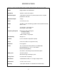
CALIBRATION AND REPAIR configuration (gain, filters and dynamic reserve setting). The figure below shows the dynamic reserve (and maximum input signal without overload) for a SR560 set to a gain of 1000, the high pass filter set to 1 kHz and the low pass filter set to 10 kHz (for a bandpass from 1 kHz to 10 kHz). The dynamic reserve characteristic is shown for both "High Dynamic Reserve" and "Low Noise" gain modes.
CALIBRATION AND REPAIR Gain Input Noise (nV/√ Hz ) Maximum DR (dB 0) 1 60 0 2 40 0 5 25 6 10, LN 10, HDR 13 25 6 14 20, LN 20, HDR 11 25 6 20 50, LN 50, HDR 10 25 14 28 100, LN 100, HDR 4 20 14 34 200, LN 200, HDR 4 18 20 40 500, LN 500, HDR 4 15 28 48 1000, LN 1000, HDR 4 15 34 54 Gain 21 Input Noise (nV/√ Hz ) Maximum DR (dB 0) 2000, LN 2000, HDR 4 10 40 52 5000, LN 5000, MDR 4 8 48 54 10000 4 54 20000 4 52 50000 4 54
CALIBRATION AND REPAIR 22
APPENDIX A 1 = 6 dB low pass, 2 = 12 dB low pass, 3 = 6 dB high pass, 4 = 12 dB highpass, 5 = bandpass REMOTE PROGRAMMING Introduction The SR560 is equipped with a standard DB25 RS-232C connector on the rear panel for remote control of all instrument functions. The interface is configured as listen-only, 9600 baud DCE, 8-bit, no parity, 2 stop bits, and is optically isolated to prevent any noise or grounding problems. Up to four SR560 amplifiers can be connected in parallel to the same RS-232 interface.
APPENDIX A A-2
APPENDIX B for carbon, R is the resistance, I the current, the bandwidth of our detector, and f is the frequency to which the detector is tuned. For a carbon resistor carrying 10 mA with R = 1 k, ∆f = f = 1 Hz, we have: NOISE SOURCES AND CURES Noise, random and uncorrelated fluctuations of electronic signals, finds its way into experiments in a variety of ways.
APPENDIX B ways which these noise sources work their way into an experiment. 3) Install capacitive shielding by placing both the experiment and the detector in a metal box. Capacitive Coupling A voltage on a nearby piece of apparatus (or operator) can couple to a detector via a stray capacitance. Although Cstray may be very small, the coupled in noise may still be larger than a weak experimental signal.
APPENDIX B The capacitance of a coaxial cable is a function of its geometry so mechanical vibrations will cause the cable capacitance to vary with time. Resistive Coupling (or ‘Ground Loops’) Currents through common connections can give rise to noise voltages. Since C = Q/V, we have: C dV + V dC = dQ = i dt dt dt So mechanical vibrations will cause a dC/dt which in turn gives rise to a current i, which will affect the detector.
APPENDIX B B-4
SR560 COMPONENT PARTS LIST Front Panel Parts List REF.
SR560 COMPONENT PARTS LIST D 48 J1 N1 N2 N3 N4 N5 P1 Q1 Q2 R1 R2 R3 R4 SW1 SW2 SW3 SW4 SW5 SW6 SW7 SW8 SW9 SW10 SW11 SW12 U1 U2 U3 U4 U5 Z0 3-00004-301 1-00035-130 4-00651-425 4-00651-425 4-00651-425 4-00336-425 4-00298-425 4-00611-452 3-00022-325 3-00021-325 4-00057-401 4-00059-401 4-00041-401 4-00081-401 2-00031-201 2-00031-201 2-00031-201 2-00031-201 2-00031-201 2-00031-201 2-00031-201 2-00031-201 2-00031-201 2-00031-201 2-00031-201 2-00031-201 3-00303-340 3-00303-340 3-00303-340 3-00303-340 3-00303-340
SR560 COMPONENT PARTS LIST C 112 C 113 C 114 C 115 C 116 C 201 C 202 C 203 C 204 C 205 C 206 C 208 C 209 C 210 C 211 C 212 C 213 C 214 C 215 C 216 C 217 C 218 C 219 C 220 C 221 C 222 C 223 C 224 C 225 C 226 C 227 C 228 C 230 C 301 C 302 C 303 C 304 C 306 C 307 C 308 C 309 C 310 C 311 C 312 C 313 C 314 C 315 C 316 C 317 C 318 5-00023-529 5-00100-517 5-00100-517 5-00100-517 5-00005-501 5-00019-501 5-00100-517 5-00100-517 5-00100-517 5-00100-517 5-00100-517 5-00010-501 5-00061-513 5-00063-513 5-00065-513 5-00
SR560 COMPONENT PARTS LIST C 319 C 320 C 321 C 322 C 323 C 324 C 325 C 326 C 327 C 328 C 330 C 401 C 402 C 403 C 404 C 405 C 406 C 407 C 408 C 409 C 410 C 411 C 412 C 413 C 414 C 415 C 416 C 417 C 418 C 502 C 503 C 703 C 704 C 705 C 706 C 707 C 708 C 709 C 710 C 711 C 712 C 713 C 714 C 715 C 716 C 717 C 718 C 801 C 802 C 803 5-00033-520 5-00033-520 5-00031-520 5-00031-520 5-00232-520 5-00232-520 5-00023-529 5-00023-529 5-00192-542 5-00192-542 5-00100-517 5-00017-501 5-00100-517 5-00100-517 5-00100-517 5-00
SR560 COMPONENT PARTS LIST C 804 C 805 C 806 C 807 C 808 C 809 C 810 C 811 C 812 C 813 C 814 C 815 C 816 C 817 C 818 C 819 C 820 C 821 C 822 C 823 C 824 C 825 C 826 C 827 C 828 C 829 C 830 C 831 C 832 D 101 D 201 D 202 D 301 D 302 D 401 D 402 D 403 D 404 D 405 D 406 D 407 D 408 D 501 D 502 D 503 D 505 D 701 D 702 D 703 D 704 5-00225-548 5-00225-548 5-00225-548 5-00225-548 5-00023-529 5-00225-548 5-00023-529 5-00225-548 5-00225-548 5-00225-548 5-00225-548 5-00225-548 5-00225-548 5-00225-548 5-00225-548 5-00
SR560 COMPONENT PARTS LIST D 705 D 706 D 707 D 708 D 709 D 710A D 710B D 711 D 801 D 802 D 803 J 101 J 102 J 404 J 405 J 601 J 805 JP801 K 101 K 102 K 103 K 104 K 105 K 201 K 301 N 701 N 702 P 101 P 102 P 103 P 104 P 701 P 702 Q 102 Q 103 Q 104 Q 105 Q 106 Q 107 Q 108 Q 109 Q 110 Q 111 Q 201 Q 202 Q 301 Q 302 Q 501 Q 701 Q 702 3-00011-303 3-00062-340 3-00226-301 3-00226-301 3-00306-340 3-00391-301 3-00391-301 3-00198-301 3-00226-301 3-00004-301 3-00004-301 1-00073-120 1-00073-120 1-00073-120 1-00073-120 1-
SR560 COMPONENT PARTS LIST Q 703 Q 801 R2 R 101 R 102 R 103 R 104 R 105 R 106 R 108 R 109 R 110 R 111 R 112 R 113 R 114 R 115 R 116 R 117 R 118 R 119 R 120 R 121 R 122 R 123 R 124 R 125 R 126 R 127 R 128 R 129 R 130 R 131 R 132 R 133 R 134 R 135 R 136 R 137 R 201 R 202 R 203 R 204 R 205 R 206 R 207 R 208 R 209 R 210 R 211 3-00374-329 3-00376-329 4-00616-453 4-00306-407 4-00306-407 4-00030-401 4-00030-401 4-00030-401 4-00030-401 4-00169-407 4-00041-401 4-00141-407 4-00217-408 4-00030-401 4-00301-408 4-00301
SR560 COMPONENT PARTS LIST R 212 R 213 R 214 R 215 R 216 R 217 R 218 R 219 R 220 R 221 R 222 R 223 R 224 R 225 R 226 R 227 R 228 R 229 R 301 R 302 R 303 R 304 R 305 R 306 R 307 R 308 R 309 R 310 R 311 R 312 R 313 R 314 R 315 R 316 R 317 R 318 R 319 R 320 R 321 R 322 R 323 R 324 R 325 R 326 R 327 R 328 R 329 R 330 R 401 R 402 4-00600-407 4-00600-407 4-00030-401 4-00165-407 4-00030-401 4-00325-407 4-00030-401 4-00030-401 4-00296-407 4-00165-407 4-00165-407 4-00140-407 4-00188-407 4-00158-407 4-00048-401 4-00
SR560 COMPONENT PARTS LIST R 403 R 404 R 405 R 406 R 407 R 408 R 409 R 410 R 411 R 412 R 413 R 415 R 416 R 417 R 418 R 419 R 420 R 421 R 422 R 423 R 424 R 425 R 426 R 427 R 428 R 429 R 430 R 431 R 432 R 433 R 434 R 435 R 436 R 437 R 438 R 439 R 440 R 441 R 442 R 501 R 502 R 503 R 602 R 603 R 701 R 702 R 703 R 704 R 705 R 706 4-00325-407 4-00165-407 4-00030-401 4-00030-401 4-00030-401 4-00317-407 4-00296-407 4-00165-407 4-00165-407 4-00296-407 4-00165-407 4-00165-407 4-00555-407 4-00030-401 4-00030-401 4-00
SR560 COMPONENT PARTS LIST R 707 R 708 R 709 R 710 R 711 R 712 R 713 R 714 R 715 R 716 R 717 R 718 R 719 R 720 R 721 R 722 R 723 R 724 R 725 R 726 R 727 R 728 R 729 R 730 R 731 R 801 R 802 R 803 R 804 R 805 R 806 R 807 R 808 R 809 R 810 R 811 R 812 R 813 R 814 R 815 R 816 R 817 SO102 SO106 SO504 SO708 SO709 SW601 SW801 T1 4-00042-401 4-00376-407 4-00169-407 4-00058-401 4-00035-401 4-00035-401 4-00612-407 4-00278-407 4-00576-407 4-00386-407 4-00614-407 4-00613-407 4-00363-407 4-00383-407 4-00615-407 4-00207
SR560 COMPONENT PARTS LIST U 101 U 102 U 103 U 104 U 105 U 106 U 201 U 202 U 203 U 204 U 205 U 301 U 302 U 303 U 304 U 305 U 401 U 402 U 403 U 404 U 405 U 406 U 407 U 408 U 409 U 501 U 502 U 503 U 505 U 506 U 507 U 508 U 509 U 510 U 601 U 602 U 603 U 604 U 605 U 606 U 607 U 701 U 702 U 703 U 704 U 705 U 706 U 707 U 708 U 709 3-00371-340 3-00382-340 3-00090-340 3-00385-340 3-00297-340 3-00246-340 3-00382-340 3-00270-340 3-00270-340 3-00189-340 3-00371-340 3-00270-340 3-00270-340 3-00189-340 3-00371-340 3-00
SR560 COMPONENT PARTS LIST U 801 U 802 U 803 U 804 Z0 Z0 Z0 Z0 Z0 Z0 Z0 Z0 Z0 Z0 Z0 Z0 Z0 Z0 Z0 Z0 Z0 Z0 Z0 Z0 Z0 Z0 Z0 Z0 Z0 Z0 Z0 Z0 Z0 Z0 Z0 Z0 Z0 Z0 Z0 Z0 Z0 Z0 Z0 Z0 Z0 Z0 Z0 Z0 Z0 Z0 3-00112-329 3-00307-340 3-00090-340 3-00250-340 0-00014-002 0-00017-002 0-00042-010 0-00043-011 0-00048-011 0-00077-030 0-00079-031 0-00089-033 0-00096-041 0-00109-050 0-00111-053 0-00122-053 0-00126-053 0-00128-053 0-00136-053 0-00153-057 0-00209-021 0-00231-043 0-00233-000 0-00237-016 0-00240-026 0-00242-026 0-00243-00
SR560 COMPONENT PARTS LIST Z0 Z0 Z0 Z0 Z0 Z0 Z0 Z0 Z0 Z0 Z0 Z0 Z0 Z0 Z0 Z0 Z0 Z0 Z0 Z0 Z0 Z0 Z0 Z0 Z0 0-00666-050 0-00667-050 1-00124-178 1-00125-179 1-00126-176 1-00127-177 1-00128-171 4-00541-435 5-00027-503 6-00004-611 6-00074-611 7-00194-715 7-00201-720 7-00222-701 7-00232-709 7-00251-720 7-00252-720 7-00257-720 7-00258-720 7-00680-720 7-00795-720 7-00796-720 9-00127-907 9-00267-917 9-00792-917 23" #18 WHITE 20" #18 WHITE 4 PIN 4 PIN .062" DIAM .062" DIAM 20 COND 130V/1200A .
SR560 COMPONENT PARTS LIST C-14