Coding with Squishy Circuits © 2017 – Squishy Circuits Store, LLC Last revised August 2017 Comments, Questions, Concerns? Please reach out at: ContactUs@SquishyCircuits.
Table of Contents Introduction .................................................................................................................................................. 2 Coding with Squishy Circuits? ................................................................................................................. 2 Learning Objectives................................................................................................................................... 2 Educator Preparation Material ...
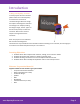
Introduction Coding with Squishy Circuits? In these projectss we use an Arduino (device similar to a small computer) to measure the resistance of conductive dough. When we change the shape of the dough the resistance also changes. For example, making the dough a longer, thinner “pipe” for the electricity to flow, increases the resistance. We can then cause an output to change based on the resistance. Note: This project is more advanced.
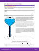
Background Knowledge Electricity and Ohms Law Electricity is the flow of charge called electrons. When describing electrical circuits, three terms are used – voltage, current, and resistance. Voltage relates to how much potential there is between the positive and negative ends. It is measured in volts. Current is a measurement of how many electrons are moving through a conductor. It is measured in amps. Resistance is how difficult it is for the electricity to flow through the conductor.
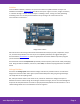
Arduino From the Arduino website, “Arduino is an open-source electronics platform based on easy-to-use hardware and software. Arduino boards are able to read inputs - light on a sensor, a finger on a button, or a Twitter message - and turn it into an output - activating a motor, turning on an LED, publishing something online. You can tell your board what to do by sending a set of instructions to the microcontroller on the board.
The equation that describes a voltage divider is: = ∗ For these projects, we know that: R1 = 470 ohms Vin = 5 volts and Vout is measured by the Arduino’s analog input. By performing some algebra, we can then rearrange the equation to find the resistance of the ∗ = = conductive dough: Breadboards Breadboards are extremely useful prototyping tools because they allow you to quickly and easily connect multiple electrical components together.
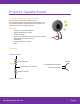
Project 1: Squishy Sound Summary and Background Knowledge The most popular example of a Squishy Circuits microprocessor project is Squishy Sound. Squishy Sound uses the conductive dough to change the pitch of a speaker – the higher the resistance, the higher the pitch.
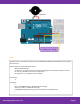
Image created with Fritzing Code: //Squishy Sound - Code written by Sam Johnson and Modified by Matthew Schmidtbauer for the Squishy Circuits Project //Port Definitions and Variable Declarations: #define SpeakerOutput 9 int analog = 0; // Common resistor connected to analog pin 0 outside leads to ground and +5V int raw = 0; // Variable to store the raw input value int frequency = 0; // Variable to store Frequency void setup() {} void loop() { raw = analogRead(analog); // Read Voltage over Dough frequency =
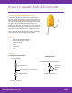
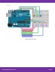
Project 2: Squishy RGB LED Controller Summary and Background Knowledge: In this project, we will use three different voltage divider circuits to control the brightness of three different LEDs. The color of the LEDs do not matter, but we have chosen to use a red, green, and blue LED which are the primary colors of light. Using them, we can make any color depending on the brightness of each color.
Figure: Image created with Fritzing www.SquishyCircuits.
Code: //Squishy RGB LED Controller //Port Definitions and Variable Declarations: #define RED_LED 9 #define GREEN_LED 10 #define BLUE_LED 11 int analog_RED = 0; // common resistor connected to analog pin 0 outside leads to ground and +5V int raw_RED = 0; // variable to store the raw input value int BRIGHTNESS_RED = 0; //Variable to store Brightness Value (0-255) int analog_GREEN = 1; // common resistor connected to analog pin 1 // outside leads to ground and +5V int raw_GREEN = 0; // variable to store the ra