NGSS Curricula and Educator’s Guide Written by: AnnMarie Thomas, Alison Haugh, Deb Besser, and Matthew Schmidtbauer Illustrations: Small Batch Creative, LLC, Shawn Smith, and Matthew Schmidtbauer Photography: Small Batch Creative, LLC © 2017 – Squishy Circuits Store, LLC Last revised June 2017 Comments, Questions, Concerns? Please reach out at: ContactUs@SquishyCircuits.
Table of Contents Introduction .................................................................................................................................................. 2 Why Squishy Circuits? ............................................................................................................................... 2 Learning Objectives...................................................................................................................................
Introduction Why Squishy Circuits? Squishy Circuits® were created in the Playful Learning Lab at the University of St. Thomas. Squishy Circuits are a design tool that allows everyone, from young children through adults, to create circuits and explore electronics using play dough. See the 2011 TED Talk, AnnMarie Thomas: Hands-on science with squishy circuits at http://squishycircuits.com/what-issquishy-circuits/ to learn more about the creator’s inspiration. Learning Objectives 1. 2. 3. 4.
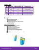
Disciplinary Core Ideas: DCI Specific DCI Grade Levels Applied Related Standards PS3 PS3.B 4,5 4-PS3-2,4 (Energy) PS3 PS3.D 4,5 4-PS3-2,4 (Energy) ETS ETS1.A 3-5 3-5-ETS1-1 (Engineering Design) ETS ETS1.B 3-5 3-5-ETS1-2,3 (Engineering Design) ETS ETS1.
Educator Preparation Material Supplies needed for each student or group of students: o o o o 4-AA Battery pack with leads Conductive dough Insulating dough 3+ LEDs Optional, but recommended: Buzzer o o Motor Switch o These materials are all available on our web store at http://squishycircuits.com/store. We offer both kits and individual components. Squishy Circuits was created to be as accessible as possible. Therefore many readily-available, low current components will work.
Background Knowledge Vocabulary Buzzers - Buzzers can be added to your Squishy Circuits by matching the red lead from the buzzer to the red lead of the battery pack and the black lead from the buzzer to the black lead of the battery pack. If desired, place a piece of tap over the top of the buzzer to reduce the volume. There are two types – mechanical and piezo. Mechanical buzzers have a plastic reed that vibrates to produce a buzz. Piezoelectric buzzers vibrate a crystal and produce a higher-pitched buzz.
Parallel Circuits - A parallel circuit allows multiple paths for electricity to flow through. LEDs or other electrical items are connected to the dough each in their own loop or circuit. Since electricity flows through each LED independently, if one is removed or burns out, the others will continue to shine brightly. Schematic – A schematic is a way to draw electrical circuits on paper easily.
Lesson 1: Sculpting Your First Circuit Summary and Background Knowledge In this lesson, students will create a functioning electrical circuit using a battery pack, LEDs, and conductive and insulating play dough. By completing student-led experiments, groups of two to three students will work together to attempt to light their LED up using the materials listed above. At the most basic level, electricity is a stream of small bits of electrical charge, called electrons.
An open circuit means that there is not a path for the electrons to flow. Try taking out one leg of the LED and you’ll notice that it turns off. This is because there is no conductor for the electrons to flow through to complete the circuit. First time Squishy Circuit users often create short circuits when exploring. These are circuits in which the electrons can simply bypass the LED and go through the conductive dough to close the circuit. Since no electrons are flowing through the LED, it stays unlit.
Time: Pair students and hand out materials: 5 minutes Discovery time (Steps 2-3): 10 minutes Sharing: 5 minutes Redesign, retest: 10 minutes Data recording: 5 minutes Total Time: 35 minutes Instructor Procedure: 1. After students have been divided into pairs or trios, provide each student with the materials listed above 2. Provide students with the following directions: a. With your partner, discuss different ways you think you could make the LED light up.
Lesson 2: Series and Parallel Circuits Summary and Background Knowledge: In this lesson, students will build on their existing knowledge regarding circuits by experimenting with Squishy Circuit materials to discover the differences between parallel and series circuits. The circuits students created in Lesson 1 were simple circuits, meaning that they comprised of a power source, a single energy output (LED or motor), and an optional switch.
A more useable example of a series circuit is to use the switch. If you put the switch in series with the LED, then the circuit will either be open or closed depending on the switch! I O Did You Know? – Many switches use ‘I’ and ‘O’ to indicate on and off. It is believed that these symbols originate from binary which uses 0 to represent off and 1 to represent on. Binary is a way to denote numbers with only 0 and 1s and is used for coding, data storage, and more. www.SquishyCircuits.
If a circuit is organized in parallel, each output (LED etc.) is independent of the others. If one output is disconnected, all others will still function. This is because they are connected on their own circuit and they all operate independently from each other. Try and think of different real-world applications for series and parallel circuits. If you have many lights in a room, typically they are connected in series with the switch – that way one switch can control all of the lights at once.
Remember, the shape of the dough does not matter. This is another example of a parallel circuit with the two pieces of conductive dough separated with a layer of insulating dough. Applicable Vocabulary: Series circuit Parallel circuit Main Objective: Upon completion of this lesson, students will be able to explain using models and verbal and/or written language the difference between series and parallel circuits, and demonstrate examples of a use for each.
Instructor Procedure: 1. After students have been divided into pairs or trios, provide each student with the materials listed above 2. Provide students with the following directions: a. With your partner, discuss different ways you think you could make the two LEDs to light up. (Use this time to investigate your materials, but don’t hook anything up yet) b. Draw in your science journal how you will attempt to solve the challenge: “Make two LEDs light up using only the materials in front of you.” c.
Lesson 3: Challenge Time! Summary and Background Knowledge: In this lesson, students will use their previously gained knowledge to construct more advanced circuits that utilize both series and parallel circuits. Then, they will transfer their circuits to paper using schematics. Schematics are a way to easily draw electrical circuits so that they can be analyzed, rebuilt, and shared.
When we built the simple circuit in Lesson 1 with a battery pack and LED, the schematic looked like this: Challenge students to build a circuit that uses both a series and parallel circuit. This circuit has a switch in series with three different LEDs in parallel. If the switch is turned off, it breaks the circuit and all three lights turn off. But, if one of the LEDs is removed, the others will continue to shine brightly because there are separate paths for the electrons to take to complete the circuit.
What if you made a car with two LED headlights in parallel, and a horn buzzer – all controlled by the switch? Its schematic could look like this: And could be made to look like this: Remember, the schematic only illustrates what electrical components are used in the circuit, and in what configuration. It does not indicate the shape or distance between them and the dough (or wires) used. www.SquishyCircuits.
Applicable Vocabulary: Schematic Main Objective: Upon completion of this lesson, students will be able to 1. Combine a series and a parallel circuit using a single battery pack 2. Create a schematic using component symbols that represent their circuits.
Squishy Circuits Dough Recipes Dough can be purchased from our online store or most purchased doughs work as conductive doughs and most modeling clays work as insulating dough. Or, recipes are below that use common household ingredients! Conductive Dough Ingredients: 1½ Cup (355 mL) Flour 1 Cup (237 mL) Water ¼ Cup (59 mL) Salt 3 Tbsp. (44 mL) Cream of Tartar* 1 Tbsp. (15 mL) Vegetable Oil Optional: food coloring *9 Tbsp.
Step 3: Continue heating and stirring until the mixture forms a ball and pulls away cleanly from the sides of the saucepan. Step 4: Turn the dough out onto a floured surface. Use caution, as it is very hot at this point. Step 5: Allow the dough to cool for a few minutes before kneading flour into it until the desired consistency is reached. Storage: Keep the dough in a sealed container or bag for several weeks. For longer periods, the dough can also be frozen.
Insulating Dough Ingredients 1½ Cup (355 mL) Flour ½ Cup (118 mL) Sugar 3 Tbsp. (44mL) Vegetable Oil ½ Cup (118 mL) Deionized Water (Note: distilled or regular tap water can be used, but the resistance of the dough will be lower) Step 1: Set aside ½ cup flour to be used later. Mix remaining flour, sugar, and oil in a pot or large bowl. Step 2: Mix in a small amount (about 1 Tbsp.) of deionized water, stirring until the water is absorbed. Repeat this step until large, sandy lumps begin to form.
Step 4: Add small increments of flour or water to yield a dough-like, pliable consistency. Storage: Keep the dough in a sealed container or bag for up to a week. For longer periods, the dough can be frozen. While in storage, the oil may separate and the dough may lose its dough-like consistency. Simply add additional flour to remove the stickiness before using again. www.SquishyCircuits.