
Installation Guide

SO2040M200S Wireway Barrier Kit, Catalog No. SO2040BAR 40273-383-02
Accesorio de barrera del ducto para cables SO2040M200S, no. de catálogo SO2040BAR 07/2005
Electrical equipment should be installed, operated, serviced, and
maintained only by qualified personnel. No responsibility is assumed by
Schneider Electric for any consequences arising out of the use of this
material.
Solamente el personal especializado deberá instalar, hacer funcionar y prestar servicios
de mantenimiento al equipo eléctrico. Schneider Electric no asume responsabilidad
alguna por las consecuencias emergentes de la utilización de este material.
Schneider Electric USA
1601 Mercer Road
Lexington, KY 40511 USA
1-888-SquareD (1-888-778-2733)
www.us.SquareD.com
Importado en México por:
Schneider Electric México, S.A. de C.V.
Calz. J. Rojo Gómez 1121-A
Col. Gpe. del Moral 09300 México, D.F.
Tel. 55-5804-5000
www.schneider-electric.com.mx
© 2005 Schneider Electric
All Rights Reserved / Reservados todos los derechos
a brand of Schneider Electric. /
una marca de Schneider Electric.
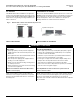
5. Install the left-hand barrier by placing the flange end
with the mounting hole in the channel next to the
meter socket and slipping the flange under the
existing meter barrier. Align the holes, reinstall the
screw, and tighten to 30 lb-in (3.4 N•m). See Figure 6.
5. Instale la barrera del lado izquierdo colocando el extremo con
reborde, con el agujero de montaje, en el canal situado al lado de la
base de medición y deslizando el reborde por debajo de la barrera
del medidor existente. Alinee los agujeros, vuelva a instalar el
tornillo y apriételo a 3,4 N•m (30 lbs-pulg). Vea la figura 6.
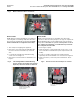
6. To install the right-hand barrier, repeat step 4. See
Figure 7.
6. Para instalar la barrera del lado derecho, repita el paso 4 (vea la
figura 7).
7. After mounting and securing both barriers, check
that the top of the barriers are at the same height as
the adjacent All-In-One meter sidewalls and exterior
sidewalls. See Figure 8.
7. Después de montar y sujetar las dos barreras, asegúrese de que
la parte superior de las barreras estén a la misma altura que las
paredes laterales y exteriores del dispositivo “Todo en uno”. Vea
la figura 8.
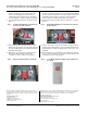
8. Mount the cover in place after completing circuit
wiring and notify the utility company of the
completion of service readiness. See Figure 9.
8. Monte la cubierta en su lugar después de completar el cableado
de los circuitos y notifique a la compañía de electricidad para que
restablezca el servicio. Vea la figura 9.
Fig. 6: Install Left-Hand Barrier / Instalación de
la barrera del lado izquierdo
Fig. 7: Install Right-Hand Barrier / Instalación de la barrera
del lado derecho
4120-9746
4120-9747
Fig. 8: Barriers Installed / Barreras instaladas Fig. 9: Cover Mounted After Installation / Reinstalación de
la cubierta
4120-9748
4120-9749