
Install Instructions
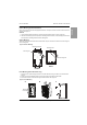
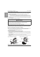
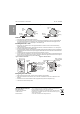
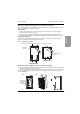
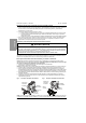
Table Of Contents
- H2G Generic Topic 2nd Level - Surface Mounting (Indoor and Outdoor)
- H2G Generic Topic 2nd Level - Outdoor
- H2G Generic Topic 2nd Level - Surface Mounting
- H2G Generic Topic 2nd Level - Flush Mounting (Indoor Enclosure Only)
- H2G Generic Topic 2nd Level - Main Circuit Breaker or Main Lug Wiring
- H2G Generic Topic 2nd Level - Branch Circuit Breaker Installation and Removal
- H2G Generic Topic 2nd Level - Standard and Tandem Branch Circuit Breakers—Installation
- H2G Generic Topic 2nd Level - Removal
- H2G Generic Topic 2nd Level - Installing the Cover / Trim
- H2G Generic Topic 2nd Level - Energizing the Load Center

QO™ and Homeline™ Load Centers Rev. 03, S1B33894
3
ENGLISH
© 2012–2021 Schneider Electric All Rights Reserved Rev. 03, S1B33894
Main Circuit Breaker or Main Lug Wiring
Branch Circuit Breaker Installation and Removal
Standard and Tandem Branch Circuit Breakers—Installation
1. Pull the conductors into the enclosure. Use approved wire clamps, conduit bushings, or other approved
methods to secure the conductor to the enclosure and prevent damage to the conductor insulation.
2. Connect the main and neutral wires.
a. Install the main and neutral wires according to the wiring diagram on the load center.
b. Connect the service ground, equipment grounding wire, or both as required by the local electrical code.
c. Torque each connection to the value specified on the load center wiring diagram attached to the enclosure.
3. If required by the local code, install the enclosed green neutral bonding screw through the hole in the neutral
bar. Thread the screw into the hole in the enclosure and torque to the value specified on the card shipped
with the bonding screw.
WARNING
HAZARD OF PERSONAL INJURY OR EQUIPMENT DAMAGE
This equipment is designed and tested by Schneider Electric™ to performance levels which meet
Underwriter’s Laboratories
®
(UL
®
) standards and Mexican Official Standards (NOM) listing.
Use only Square D™ brand circuit breakers and accessories.
Failure to follow these instructions can result in death or serious injury.
NOTE: See separate instruction bulletins included with advanced function circuit breakers and accessories for
their installation. QOP type circuit breakers are only acceptable for use on QO plug-on neutral load centers.
NOTE: Install QOT and HOMT tandem-type circuit breakers only in single-phase load centers marked for use with
tandem circuit breakers. Refer to the wiring diagram on the load center for the installation location.
1. Determine the wiring or conduit requirements for the branch circuit.
2. Turn OFF (O) the circuit breaker.
NOTE: For QOT CTL tandem only: hold the circuit breaker at 30–45° angle.
3. Install the wire terminal end of the circuit breaker onto the mounting rail.
4. Rotate the circuit breaker inward until the plug-on jaw fully engages the bus bar connector. Keep the bottom of
the circuit breaker’s case against the mounting rail. Check the terminal end of the circuit breaker for engagement
to the mounting rail.
5. Remove the wire insulation from the branch wire as required. Install the branch wire into the load terminal of the
branch circuit breaker.
6. Torque each branch circuit breaker connection to the value specified on the circuit breaker.
7. Torque each neutral and ground connection to the value specified on the load center wiring diagram attached to
the enclosure.
Figure 4: QO Standard Circuit Breaker Figure 5: QO Tandem Circuit Breaker
NOTE: Non-class CTL tandem circuit breaker shown. QOT class CTL tandem circuit breaker (not shown)
cannot be installed on a plug-on neutral load center (metal mounting rail).
Wire
terminal
end
Plug-on
jaw
Bus bar
connector
Mounting rail
(plastic only)
Plug-on
jaw
Mounting
rail
Bus bar
connector
Wire
terminal
end