
Install Instructions


© 2005 Schneider Electric USA All Rights Reserved
QO
®
and Homeline
®
Outdoor Load Centers 40271-887-03
Instruction Bulletin 03/2005
2
ENGLISH
BOX MOUNTING
Surface Mounting
1. Use the sealing gaskets provided if the mounting knockout locations shown in Figure 2
are used.
2. Fasten the box to the wall with screws or nails using one mounting hole at the top and two
mounting holes at the bottom or using two mounting knockout holes and two mounting holes at
the bottom. See Figure 2.
MAIN CIRCUIT BREAKER OR MAIN LUG WIRING
1. Pull the conductors into the box. Use approved wire clamps, conduit bushings, or other
approved methods to secure the conductors to the box and prevent damage to the
conductor insulation.
2. Connect the main and neutral conductors.
a. Install the main and neutral conductors according to the load center wiring diagram.
b. Connect the service ground, equipment grounding conductor, or both as required by
local electrical code.
c. Torque each terminal to the value specified on the load center wiring diagram
attached to the box.
3. If required by local code, install the enclosed green neutral bonding screw through the hole in
the neutral bar. Thread the screw into the hole in the box and torque to the value specified on
the card shipped with the bonding screw.
BRANCH CIRCUIT BREAKER INSTALLATION AND REMOVAL
Standard Branch Circuit Breakers—Installation
1. Determine the wiring or conduit requirements for the circuit breaker.
2. Turn OFF (O) the circuit breaker.
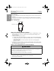
WARNING
HAZARD OF PERSONAL INJURY OR EQUIPMENT DAMAGE
This equipment is designed and tested by Square D
®
to performance levels which exceed Underwriter’s
Laboratories (UL) standards and Mexican Official Standards (NOM) listing.
Use only Square D circuit breakers and accessories.
Failure to follow this instruction can result in death or serious injury.
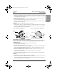
Mounting knockouts
Mounting hole
Mounting holes
11003025
Figure 2: Mounting the Box
40271-887-03.fm Page 2 Monday, March 14, 2005 12:15 PM