ELECTRONIC MARKER User Manual English Français
English ELECTRONIC MARKER TABLE OF CONTENTS IMPORTANT SAFETY GUIDELINES 2 OPERATION GUIDE / START UP 3 8 STEPS TO START AND PLAY 4-5 CRITICAL SAFETY INFORMATION 6 RECOMMENDED PAINTBALL SAFETY GEAR 7 CO2 / COMPRESSED AIR TANK WARNINGS 8 INSTALLING/REMOVING A CO2 / COMPRESSED AIR TANK 9 E-MR5 BARREL INSTALL / REMOVE / SETUP 9 PROPER USE OF YOUR BARREL BLOCKING DEVICE 9-10 BATTERY INSTALLATION/ CHARGING INSTRUCTIONS 10 LEAP 3 CIRCUIT BOARD w/C.A.M.D.
IMPORTANT SAF Y GUIDELIN WARNING • This paintball Marker is NOT a toy. Misuse can cause serious injury or death. • Spyder recommends that the customer must be at least 18 years of age to purchase this product. Person under 18 years of age must have adult supervision when using this product. • Read this User manual before using this product.
English OPERATION GUIDE / START UP 1. Always attach a barrel blocking device over the tip of the barrel for safety precautions when not shooting/ playing. 2. Install and Charge the Battery (SEE BATTERY INSTALLATION) 3. Attach a CO2/Compressed Air Tank to the Markers C/A adapter. Using a CO2/Compressed Air Tank firmly tighten clockwise to the Markers C/A adapter until it is snug. HELPFUL TIP: Make sure to have the CO2/ Compressed Air Tank filled before attaching.
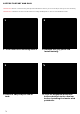
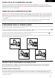
8 STEPS TO START AND PLAY IMPORTANT: Please read the Safety and Operation Guidelines before you start the 8 quick steps to Start and Play. IMPORTANT: The Barrel must be installed before loading the Magazine or Force Feed Paintball Loader. 1 1. Insert the barrel blocking device. 3 3. Install a CO2/Compressed air tank. 4 2 2. Remove left grip panel and install battery. 4 4. First fill magazine with paintballs and attach to the receiver before installing the loader with paintballs.
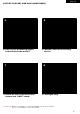
English 8 STEPS TO START AND PLAY (CONTINUED) 5 5. Put on your paintball goggles and cock back the marker. 7 7. Power on the circuit board and remove the “SAFE” mode. 6 6. Remove the barrel blocking device. 8 8. Ready to play. IMPORTANT: Make sure the Marker is in the SAFE MODE and the barrel blocking device is on the Marker’s barrel after PLAY.
CRITICAL SAFETY INFORMATION NEVER look down the barrel with or without your paintball goggles ON. NEVER look down the barrel of a loaded or unloaded marker. WARNING: UNSAFE NEVER shoot or point your marker at a person that is not in a designated paintball facility and without proper EYES/FACE/EARS protection designed specifically for the sport of paintball. *Paintball marker model shown is for demonstration only and may not represent the marker model you have.
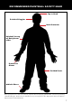
RECOMMENDED PAINTBALL SAFETY GEAR Cap or Hood Paintball Goggles Neck Protector Paintball Jersey w/ Body Armor under Protective Gloves Padded Pants Athletic Shoes Wear appropriate dress attire to avoid any exposed skin when playing paintball. We recommend purchasing a Paintball Goggles, Neck Protector, Paintball Jersey or Long Sleeve shirt, Body Armor, Protective Gloves, Athletic Shoes and Padded Pants.
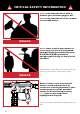
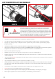
CO2 / COMPRESSED AIR TANK WARNINGS SAFE DAN GER UNSAFE The CO2 or Compressed Air Tank can fly off with enough force to cause serious injury or death if the Valve unscrews from the cylinder head. LOOK at the Valve when removing the cylinder from the marker. Be sure that the valve is turning with the cylinder rather than remaining stationary with the marker. STOP if the Valve starts to unscrew from the cylinder. If in doubt, screw the cylinder back onto the marker and contact a trained person for repair.
English INSTALLING A CO2 / COMPRESSED AIR TANK Firmly screw the CO2 / Compressed Air Tank clockwise into the markers C/A Adapter. HELPFUL TIP: Before installing a CO2 / Compressed Air Tank, make sure that the tank is full and that it has a urethane bottle O-ring on the top of the valve to prevent air leaks. IMPORTANT: You should never need to use any hand tool to attach a CO2 / Compressed Air Tank to the C/A Adapter.
BARREL PLUG TYPE DEVICE Insert the barrel plug securely into the end of your markers barrel before proceeding to load paintballs and screwing in your tank to your marker. The barrel plug should fit firmly into the barrel with a significant amount of resistance. NOTE: The barrel plug should not be easy to remove and always inspect the O-rings to make sure they are not worn or cut.
English LEAP 3 CIRCUIT BOARD w/C.A.M.D. SETTINGS SAFE – Red LED SEMI – Green LED 3 Burst – Blue LED 6 Burst – Blue LED AUTO – Orange LED BATTERY ICON – Yellow LED (Solid LED = Good, Flashing LED = Low) 2 BUTTON ACCESS OPERATIONS Press and release the Upper “Power” Button to turn the Marker “On”. The C.A.M.D. Board will display the Red “Safe” indicator “On” meaning that the Marker is in safety mode and will not allow the Marker to shoot.
TRIGGER ADJUSTMENT STEP 1 Adjusting the Top Trigger Screw located underneath the Trigger Frame clockwise will swing the Trigger closer to the touch switch. NOTE: Adjusting the Top Trigger screw counter-clockwise will increase the trigger gap. IMPORTANT: Over adjusting the Trigger screw to close won’t allow the trigger to activate the touch switch which will not allow the Marker to fire. STEP 2 Adjusting the Middle Trigger Screw clockwise will shorten the trigger stop from the touch switch.
English MAGAZINE LOADING PAINTB IMPORTANT: The Barrel must be installed before loading the Magazine or Force Feed Paintball Loader. IMPORTANT: Always have the marker on SAFE MODE until you are ready to operate. IMPORTANT: Storing paintballs in a temperature of 59° F (15°C) or below will affect the quality and performance of the paintballs. IMPORTANT: The magazine should be clean and free of any shell fragment or dirt before loading paintballs. WARNING: DO NOT attempt to Freeze any Paintballs.
INSTALLING / REMOVING THE SOPMOD STOCK Place the SOPMOD Stock in the top breach of the Receiver behind the FS Venturi Bolt. Once the SOPMOD Stock is in place secure the Stock with the set screw provided, then tighten with the Allen wrench. To adjust the length of the SOPMOD Stock press and hold the Lever for adjustment. Once the Lever is released this will lock into position. Loosen the set screw on the right side of the Receiver with the Allen wrench.
English DANGER: Do not look down the Marker barrel. Always wear goggles specifically designed for paintball use while working on your paintball Marker. IMPORTANT: Always have the Marker on SAFE MODE before disassembly. Remove all paintballs and air source from the Marker before performing any maintenance. HELPFUL TIP: Follow these steps to help clean/remove Marker parts should in the event of a paintball break.
Reassemble Rear Internals STEP 1 Join both FS Venturi Bolt and Striker Bolt thru the rear of the Receiver with the O-ring on the Striker Bolt facing towards the front of the Marker. NOTE: When inserting both parts, apply finger pressure behind the FS Venturi Bolt and at the same time pull on the Trigger to allow entry of the both parts. STEP 2 Insert the Striker Buffer flush at the lower end of the Receiver and place the Striker Spring thru the Striker Buffer.
English Eko™ CUP SEAL REMOVAL SCR057 SCR037 ITP026 ITP023 LPC089 SCR016 SPR016 Swivel End Part Names and Numbers describe in this section: Screw (#SCR016) Vertical Screw (#SCR037) Screw (#SCR057) Eko™ Valve Pin (#ITP026) Valve Spring (#SPR016) Eko™ Cup Seal (#ITP023) Reservoir Plug (#LPC089) The following steps will provide easy access to the Eko™ Cup Seal. The sign of a worn out Eko™ Cup Seal is the presence of CO2 / Compressed Air leaking down the barrel.
TROUBLESHOOTING Air Leak From The Hose Line 1. If air is leaking from the opposite ends of the hose fittings will need to retighten to snug. 2. The female end of the hose must have a Plastic Washer installed inside the Hose collar and be tightened properly. IMPORTANT: The Hose line supplied has metric female ends. This will not install into American 1/8” (NPT) threaded fittings. If installed incorrectly, it is possible to damage the attachment fittings and hose line.
English WARRANTY ATEMENT Spyder warrants the original retail purchaser that this product is free from defects in material and workmanship under normal use and service for a period of (1) year from the original date of purchase. Any Electronic Components in an Electronic Spyder marker are warranted for (6) months from the original date of purchase. Spyder agrees to repair or replace (at its discretion) any product within (a reasonable period of time).
E-MR5™ PARTS LIST 1 ASA036 C/A Adapter Angled 43 SCR018 M3 x 8 Screw (+) 2 BAR002 Orange Blaze Rubber Ring 44 SCR024 M5 x 25 Screw C/A Adapter (A) 3 BAR003 Spyder Barrel Plug 45 SCR029 M4 x 6 Venturi Bolt Screw (A) 4 BLS039 Barrel Ball Stopper 46 SCR037 M4 x 12 Vertical Screw (AFH) 5 ECB015 LEAP 3 Circuit Board w/CAMD 47 SCR045 M4 x 14 Feed Neck Screw (A) 6 ELM001 Coil Set 48 SCR048 Feed Neck Clamp Screw (A) & Nut 7 ELM002 Coil Pin 49 SCR050 M4 x 16 Magazine Screw (+) 8 E
39 5 39 2 9 8 73 83 3 33 15 59 69 38 36 27 80 60 52 82 68 51 24 74 72 7 53 41 10 6 38 26 12 21 4 77 78 23 78 13 56 11 50 14 57 22 26 51 30 26 47 48 34 55 46 76 49 28 20 42 17 40 64 18 65 68 32 63 19 28 51 42 25 58 44 1 81 35 26 42 61 66 26 62 70 43 54 79 37 71 45 16 29 67 43 English E-MR5™ SCHEMATICS 21
MR™ ACCESSORIES 14” FS Battle Barrel #31254 18” FS Sniper Barrel #31256 Features include: • AR15 Birdcage Style Muzzle Brake w/ Standard Threading Compatible w/ E-E-MR5™, E-MR5™, MRX™ & MRX™ Elite • • First Strike™ Capable (FSC) * MRX™ & MRX™ Elite need the MRX™ G2 Venturi Bolt (#31259) to use this barrel Features include: • AR15 Birdcage Style Muzzle Brake w/ Standard Threading Compatible w/ E-E-MR5™, E-MR5™, MRX™ & MRX™ Elite • • First Strike™ Capable (FSC) * MRX™ & MRX™ Elite need the MRX™ G2 Venturi
English MR™ ACCESSORIES MR™ Barrel Shroud #31251 M4A1 Style Barrel Shroud Features include: M4 Style Oval Heat Shield w/ 14 Slot Bottom RIS (B14) • Compatible w/ E-E-MR5™ & E-MR5™ • • 12” CQB Barrel Requires Front Shroud Base #31244 Front Shroud Base #31244 Sling Plate #31253 M4A1 Style Front Shroud Base Rear Single Point Features include: M4A1 Style, Front Shroud Base Ring Eliminates the FSB, • w/ Delta Ring Eyelet • Compatible w/ MR™ Barrel Shroud, Quad RIS Barrel Shroud, MRX™ Barrel Shroud 10 Rou
Français ELECTRONIC MARKER TABLE DES MATIERES IMPORTANTES CONSIGNES DE SECURITE 26 MISE EN ROUTE 27 8 ÉTAPES POUR COMMENCER À JOUER 28-29 INFORMATIONS IMPORTANTES DE SÉCURITÉ 30 ÉQUIPEMENT DE SÉCURITÉ RECOMMANDÉ POUR LE PAINTBALL 31 CONSIGNE DE SECURITE SUR LA BOUTEILLE DE CO2/AIR COMPRIMEE 32 DEMONTER UNE BOUTEILLE DE CO2/AIR COMPRIME 33 INSTALLER / DÉMONTER / MONTER LE BARIL E-MR5 33 UTILISATION APPROPRIEE DU BOUCHON DE CANON 33-34 INSTALLATION DE LA PILE / CHARGEMENT DE LA PILE 34 R
IMPORT C ECURITE WARNING • Ce marqueur de paintball n’est PAS un jouet. Une mauvaise utilisation peut entraîner des blessures graves ou la mort. • Spyder recommande que le client ait au moins 18 ans pour acheter ce produit. Les personnes de moins de 18 ans doivent être surveillées par un adulte lorsqu’elles utilisent ce produit. • Veuillez lire ce manuel de l’utilisateur avant d’utiliser ce produit.
Français MISE EN ROUTE ATTENTION: Toujours garder son lanceur éteint ou sur le mode “safe” jusqu’a son utilisation. 1. Toujours mettre un bouchon de canon en bout de canon pour des raisons de sécurité quand le lanceur n’est pas utilisé. 2. Installer et charger le pile (Coir chapitre INSTALLATION DE LA PILE, DE SON CHARGEMENT) 3. Attacher la bouteille de CO2 ou d’air comprimé à l’adaptateur. CONSEIL: Assurez-vous que la bouteille de CO2 ou d’air comprimé soit remplie avant de la monter au lanceur.
8 ÉTAPES POUR COMMENCER À JOUER IMPORTANT: Lire les recommandations de sécurité et de fonctionnement avant de suivre les 8 étapes rapides pour commencer à jouer. IMPORTANT: Le canon doit être installé avant de charger le Magazine ou le chargeur de Paintball. 1 1. Insérez le systéme de blocage du canon. 3 3. Installez une bouteille de CO2 / d’air comprimé. 28 2 2. Installez une pile dans poigneé. 4 4. Installez le chargeur de paintball ou le magazine et le remplir avec des balles de peinture.
Français 8 ÉTAPES POUR COMMENCER À JOUER (continuer) 5 5. Mettez vos lunettes de paintball et armez le marqueur. 7 7. Mettez la carte de circuit sous tension et déverrouillez la mode sécurité. 6 6. Retirez le systéme de blocage du canon. 8 8. Prêt à jouer et tirer.
INFORMATIONS IMPORTANTES DE SÉCURITÉ Ne JAMAIS regarder le fût du lanceur de paintball avec ou sans vos lunettes de protection. Ne JAMAIS regarder le fût d’un lanceur de paintball qu’il soit chargé ou non. WARNING: UNSAFE Ne JAMAIS viser une personne ou tirer avec votre lanceur sur une personne ne portant pas l’équipement requis pour le paintball et sans les protections pour les YEUX/VISAGE/OREILLES (masque de paintball), spécifiquement conçues pour pratiquer le paintball.
Français ÉQUIPEMENT DE SÉCURITÉ RECOMMANDÉ POUR LE PAINTBALL Casquette ou casque Lunettes de paintball Protège-cou Chandail de paintball avec plastron en dessous Gants de protection Pantalon épais Chaussures de randonnée Utiliser la combinaison appropriée afin d’éviter tout contact avec la peau durant la partie de paintball.
CONSIGNE DE SECURITE SUR LA BOUTEILLE DE CO2/AIR COMPRIME SAFE DAN GER WARNING: UNSAFE La bouteille de CO2 ou d’air comprimé peut partir avec assez de force pour causer des blessures graves ou la mort si la valve se détache de la bouteille. Toujours regarder la valve en devisant la bouteille, en s’assurant que la valve tourne avec la bouteille et ne reste pas sans bouger contre l’adaptateur on/off. Arrêter le démontage si la valve commence à se dévisser de la bouteille.
Français DEMONTER UNE BOUTEILLE DE CO2/AIR COMPRIME Dévisser la bouteille de CO2 ou d’air comprimé de l’adaptateur en tournant dans le sens inverse des aiguilles d’une montre. CONSEIL: Après l’utilisation vous devriez toujours démonter la source de gaz de votre lanceur. Quand la bouteille est démontée de l’adaptateur, un excèdent de gaz est purge par le dessous. PRECAUTION: Ne jamais exposer la peau en dessous de l’adaptateur où se trouve le trou d évacuation lors du démontage.
BOUCHON DE TYPE “BOUCHON RIGIDE” (continuer) doit pas être facile a enlever et il faut toujours inspecter les joints toriques pour s’assurer qu’ils ne soient pas abîmés ou coupées. N’enlevez le bouchon de canon que quand vous êtes prêt à jouer ou si un agent de sécurité du terrain vous donne l’autorisation de le faire.
Français REGLAGES DE LA CARTE ELECTRONQUE «LEAP 3» AVEC ECRAN «C.A.M.D» SAFE – Rouge LED SEMI – Verte LED 3 Burst – Bleu LED 6 Burst – Bleu LED AUTO – Orange LED BATTERY ICON – Jaune LED (couleur unie LED = bon, clignotant LED = faible) LES 2 BOUTONS DE PARAMETRAGE Pressez le bouton du haut “Power” pour allumer le lanceur. L’écran CAMD affichera le voyant rouge “safe” et le voyant « ON » , ce qui signifie que le lanceur est allumer mais avec la sécurité enclenchée donc le lanceur ne tirera pas.
REGLAGE DE DÉTENTE ÉTAPE 1: Agissant sur la vis de détente haut située sous le cadre de la gâchette vers la droite se balancera la gâchette plus près de l’interrupteur tactile. NOTE: Agissant sur la vis de détente haut dans le sens antihoraire augmentera l’écart de la gâchette. IMPORTANT: Sur la gâchette de réglage vis pour fermer ne permettra le déclencheur activer ÉTAPE 2: l’interrupteur tactile qui ne permettra pas le marqueur au feu.
Français CHARGEMENT DES BILLES DANS LE MAGAZINE IMPORTANT: Le canon doit être installé avant de charger le Magazine ou le chargeur de Paintball. IMPORTANT: Tant que vous n’êtes pas prêt à jouer, le marqueur doit toujours être en MODE SECURITE. IMPORTANT: Stocker les billes de paintball à une température de 15° C (59° F) en affectera la qualité et la performance. IMPORTANT: Le chargeur doit être propre et vous devez tirez tout fragment de cartouche ou poussière avant de charger les billes de paintball.
MONTAGE/DÉMONTAGE D’UN SOPMOD STOCK Placez le SOPMOD Stock dans la violation haut du récepteur derrière la culasse FS Venturi. Une fois le SOPMOD Stock en place assurer le Stock avec la vis sans fourni, puis serrez avec la clé Allen. Pour ajuster la longueur de la presse SOPMOD Stock et tenir le levier de réglage. Une fois que le levier est sorti il se bloque en position. Desserrez la vis fixe sur le côté droit du récepteur avec la clé Allen.
Français depuis l’avant du lanceur en faisant attention que la surface en contact avec le devant de la culasse soit plat pour ne pas endommager la culasse ou l’alésage du corps. Après avoir débloqué la culasse d’une manière ou d’une autre, nettoyez la chambre de la bille et la culasse si nécessaire pour assurer des performances optimums. DANGER: Ne pas regarder dans le canon du marqueur. Toujours porter des lunettes spécialement conçues pour les marqueurs de paintball, dès que vous manipulez votre marqueur.
DEMONTAGE DES PIECES INTERNES ARRIERES (continuer) ÉTAPE 2: Retirer l’obturateur du percuteur, le ressort du percuteur et le butoir du percuteur de l’arrière du récepteur. ÉTAPE 3: Inclinez l’arrière du marquer dans vos mains pour attraper la culasse FS Venturi Bolt et le verrou du percuteur situés à l’arrière du récepteur. CONSEIL: nettoyez l’intérieur du corps a l’aide d’une tige, nettoyez également le marteau et la culasse en remettant quelque goûtes d’huile sur le joint torique rouge du marteau.
Français GUIDE DE DEMONTAGE DU Eko™ CUP SEAL SCR057 SCR037 ITP026 ITP023 LPC089 SCR016 SPR016 Swivel End Noms et des numéros de pièces dans cette section: Screw (#SCR016) Vertical Screw (#SCR037) Screw (#SCR057) Eko™ Valve Pin (#ITP026) Valve Spring (#SPR016) Eko™ Cup Seal (#ITP023) Reservoir Plug (#LPC089) Les étapes suivantes vous permettrons d’accéder facilement au « Eko™ Cup Seal ». Une fuite d’air ou de CO2 au canon est le signe d’ un « Eko™ Cup Seal » abîmé.
DÉPANNER FUITE D’AIR DU TUYAU 1. Si la fuite d’air se situe à l’extrémité opposée du tuyau, les raccords auront besoin d’être resserrés pour être bien ajustés. 2. L’extrémité femelle du tuyau doit être équipée d’une rondelle en plastique à l’intérieur du collier de serrage et doit être bien serrée. IMPORTANT: Le tuyau fourni a des extrémités femelles métriques. Il ne sera pas possible de le brancher à un raccord fileté américain 1/8” (NPT).
Français POLICE DE GARANTIE Spyder garanti au client original ce produit pour une période de 1 ans à partir de la date d’achat, garantie pièce et main d’œuvre en cas de défaillance sous réserve que le produit est été utilisé dans des conditions normales. Toute pièce électronique dans les lanceurs Spyder électronique est garantie 6 mois à partir de la date d’achat. Spyder accepte de réparer ou remplacer à sa discrétion tout produit dans une période de temps raisonnable.
LISTE DES PIECES DU SPYDER E-MR5™ 1 ASA036 C/A Adapter Angled 43 SCR018 M3 x 8 Screw (+) 2 BAR002 Orange Blaze Rubber Ring 44 SCR024 M5 x 25 Screw C/A Adapter (A) 3 BAR003 Spyder Barrel Plug 45 SCR029 M4 x 6 Venturi Bolt Screw (A) 4 BLS039 Barrel Ball Stopper 46 SCR037 M4 x 12 Vertical Screw (AFH) 5 ECB015 LEAP 3 Circuit Board w/CAMD 47 SCR045 M4 x 14 Feed Neck Screw (A) 6 ELM001 Coil Set 48 SCR048 Feed Neck Clamp Screw (A) & Nut 7 ELM002 Coil Pin 49 SCR050 M4 x 16 Magazine
39 5 39 2 9 8 73 83 3 33 15 59 69 38 36 27 80 60 52 82 68 51 24 74 72 7 53 41 10 6 38 26 12 21 4 77 78 23 78 13 56 11 50 14 57 22 26 51 30 26 47 48 34 55 46 76 49 28 20 42 17 40 64 18 65 68 32 63 19 28 51 42 25 58 44 1 81 35 26 42 61 66 26 62 70 43 54 79 37 71 45 16 29 67 43 Français SCHÈMAS DU SPYDER E-MR5™ 45
Distributed by KEE Action Sports / 1-800-PAINTBALL / www.keeactionsports.