USER MANUAL English Français Español
English .
IMPORTANT SAFETY GUIDELINES WARNING • This paintball marker is NOT a toy. It can cause serious injury or death. • Kingman recommends that the customer be at least 18 years of age to purchase this product. • Read this manual and air tank warnings before using this product. • Any modifications or tampering of original factory parts will void all warranties and liabilities from Kingman. • Kingman recommends using a barrel blocking device when the marker is not in operation.
English OPERATION GUIDE / START UP WARNING: Always keep the marker powered OFF or on SAFE until you are ready to fire. 1. 2. 3. 4. 5. 6. 7. 8. 9. 10. 11. 12. 13. Always attach a barrel blocking device over the tip of the barrel for safety precautions when the marker is not in use. Install and charge the battery see pages (See Battery Installation) Attach a CO2 / Compressed Air Tank to the C/A On/Off Adapter.
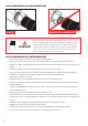
CO2 / COMPRESSED AIR TANK WARNINGS SAFE WARNING:UNSAFE DANGER The CO2 or Compressed Air Tank can fly off with enough force to cause serious injury or death if the Valve unscrews from the cylinder head. LOOK at the Valve when removing the cylinder from the marker. Be sure that the valve is turning with the cylinder rather than remaining stationary with the marker. STOP if the Valve starts to unscrew from the cylinder.
English INSTALLING A CO2 / COMPRESSED AIR TANK Firmly hand tighten the CO2 / Compressed Air Tank clockwise into the markers C/A On/Off adapter. HELPFUL TIP: Before installing a CO2 / Compressed Air Tank, make sure that the tank is full and that it has a urethane bottle o-ring on the top of the valve to prevent air leaks. IMPORTANT: You should never need to use any hand tool to attach a CO2 / Compressed Air Tank to the C/A On/Off adapter.
BATTERY INSTALLATION SCR002 WRH002 GRP005 SCR002 Part Names and Numbers described in this section: Dual Texture Grip Panel (#GRP005) M4 x 8 Screw (A) (#SCR002) Battery Harness (#WRH002) BATTERY INSTALLATION Kingman Group recommends using a Spyder 9.6volt NiMH Rechargeable Battery as a power source for optimum performance and will provide a superior shot count of around 5000 to 6000 rounds.
English CHARGING INSTRUCTIONS Spyder 9.6volt Battery (US LED) optional accessory To charge a Spyder 9.6 NiMH battery, the circuit board must be in the OFF position. Spyder batteries (JE1015) are not fully charged when purchased. Using the supplied Spyder LED A/C Charger (JE1029), plug the charger into the charger port located at the rear of the trigger frame. For a complete charge, Kingman recommends a charging time of 6-8 hours. STEP 1 Plug the Spyder LED A/C charger into a power outlet.
LEAP™ CIRCUIT BOARD w/CAMD SETTINGS SAFE – Red LED SEMI – Green LED RAMP P – Blue LED (PSP RAMP) 13 Balls Per Second RAMP M – Blue LED (Millennium RAMP) 12 Balls Per Second EYE – Orange LED (LED ON = Eyes ON, LED OFF = Eyes OFF) BATTERY – Yellow LED (Solid LED = Good, Flashing LED = Low) CAMD Display UPPER Button LOWER Button 2 BUTTON ACCESS OPERATIONS Press and release the Upper “Power/Eye” Button to turn the marker “On”.
English WARNING • Spyder Electronic Markers are not water resistant. • Extreme moisture can cause serious damage to any Spyder Electronic Marker. • Always clean any dirt or paint inside the markers electronics. • Never attempt to modify the electronics circuitry, doing so will VOID all electronic warranties and liabilities from Kingman.
C/A ON/OFF ADAPTER HELPFUL TIP: Make sure to have the C02 / Compressed Air Tank filled before use. • • • • Firmly, hand tighten the CO2 / Compressed Air Tank clockwise into the markers C/A On/Off adapter. Tighten the tank clockwise in the markers C/A On/Off adapter until it is snug. If an air leak occurs between the tank and the C/A On/Off adapter, replace the urethane o-ring. To pressurize the marker turn the adapter knob towards the ON position to pierce the pin valve on the tank.
Adjustment to the regulator output pressure is done through the regulator adjuster knob located at the bottom of the regulator with the use of the wrench provided with the spare parts kit. STEP 1 Loosen the Regulator Adjuster Lock Screw located on the on the Regulator Adjuster Knob.
DISASSEMBLE / REASSEMBLE AND CLEANING OF REAR INTERNALS VBT008 STK008 STF001 REC030 REC031 SPR004 STP028 STP029 STB002 Part Names and Numbers described in this section: Top Cocking Knob (#STK008) Delrin Bolt (#VBT008) Striker Bolt (#STB002) Striker Plug (#STP028/STP029) Striker Spring (#SPR004) Striker Buffer (#STF001) Receiver (#REC030/REC031) QUICK CLEAN DISASSEMBLY Lift upward on the Top Cocking Knob to disconnect the Delrin Bolt from the Striker Bolt.
English REASSEMBLY REAR INTERNALS CONNECTED DISCONNECTED STEP 1 Reinsert the Striker Bolt with Striker O-ring facing toward the front of the marker with the flat spot of the Striker Bolt facing down. NOTE: Having the Power Switch ON will ease reentry of the Striker Bolt. Apply thumb pressure behind the Bolt and at the same time pull on the Trigger. Repeat this process until the Bolt is fully inserted. NOTE: The hole on the Striker Bolt should be facing upright when looking thru the Receiver.
ANTI CHOP EYES BLS003 BLS 011 BLS012 BLS014 BLS015 WRH008 SCR002 Part Names and Numbers described in this section: Eye Panel (#BLS011/BLS012/ BLS014/BLS015) Ball Stopper (#BLS003) Eye Panel Screw (#SCR002) Eye Wire Harness (#WRH008) ANTI CHOP EYES The Anti Chop Eyes help prevent the chopping of paint by not allowing the marker to fire until a paintball is properly chambered in the breach. The Eyes transmit a beam across the inside of the breech.
English CUP SEAL REMOVAL ITP012 LPC028 LPC029 SPR013 ITP011 ITP017 VRT028 VRT029 ITP019 SCR027 REG028 REG029 Part Names and Numbers described in this section: Regulator (#REG028/REG029) Cup Seal Guide (#ITP011) Cup Seal (#ITP012) Valve Pin (#ITP017) M5x20 Vertical Washer (#ITP019) Front Plug (#LPC028/LPC029) Valve Spring (#SPR013) Vertical Adapter (#VRT028/VRT029) Vertical Adapter Mounting Screw (#SCR027) STEP BY STEP CUP SEAL ACCESS Access of the cup seal for service or replacement requires the remo
TROUBLESHOOTING ONE OR MORE OF THE FOLLOWING MAY CAUSE RECOCKING RELATED ISSUES: • Need lubrication on the following O-ring (#ORG001) (see Disassemble / Reassemble). • The pressure in the tank is too low and possibly needs to be refilled. • Striker O-ring (#ORG001) is damaged or missing. Replace with a new Kingman approved Striker O-ring. NOTE: The Striker O-ring can not be substituted with a black or urethane bottle o-ring.
English REGULATOR SCHEMATIC ORG025 REG008 REG009 ORG022 SCR025 REG003 REG004 REG014 ORG024 REG010 REG011 ORG024 REG012 REG013 SCR026 16
ELECTRA w/Eye PARTS LIST ASA023 ASA021 ASA024 ASA018 ASA030 ASA031 BAR028 BAR029 BLS003 BLS009 BLS010 BLS011 BLS012 BLS014 BLS015 ECB008 ELM001 ELM002 ELM003 ELM004 ELM008 ELM009 FND010 FND012 FND030 FND031 GRP005 HSE010 HSF004 HSF009 ITP011 ITP012 ITP017 ITP018 ITP019 LPC028 LPC029 ORG001 ORG002 ORG003 ORG006 ORG008 ORG010 ORG018 ORG021 ORG022 ORG023 ORG024 * PAK005 17 C/A On/Off Adapter Knob (polished black) C/A On/Off Retaining Screw C/A On/Off Adapter Knob (polished titanium) C/A On/Off 1/8 Hose Plug
English ELECTRA w/Eye SCHEMATICS STP028 STP029 RPN002 RPN001 WRH007 ORG002 SCR011 ELM001 ELM002 STF001 SCR029 ORG008 ELM004 VTA028 VTA029 VBT013 SCR003 VBT004 SPR004 STK008 ECB008 TRS008 VBT003 STB002 ELM003 BLS009 BLS010 BLS003 VBT008 SCR003 SCR002 BLS011 BLS012 BLS014 BLS015 ORG001 SCR030 REC030 REC031 SCR028 SCR002 SER001 WRH008 FND010 FND012 SCR007 FND030 FND031 ORG002 ORG003 ITP018 ORG023 VRT028 ORG002 VRT029 ITP017 GRP005 SCR028 TRF009 SCR027 ASA023 ASA024 HSF009 ASA030 ASA03
WARRANTY STATEMENT Kingman warrants the original retail purchaser that this product is free from defects in material and workmanship under normal use and service for a period of (1) year from the original date of purchase. Any Electronic Components in an Electronic Spyder marker are warranted for (6) months from the original date of purchase. Kingman agrees to repair or replace (at its discretion) any product within (a reasonable period of time). This warranty does not cover o-rings, cup seals, 9.
Français Marqueur Electronique De Paintball De Calibre .
IMPORTANTES CONSIGNES DE SECURITE ATTENTION 23 • Ce lanceur de paintball n’est pas un jouet, il peut provoquer des blessures grave voir la mort. • Kingman recommande que le client soit agé d’au moins 18 ans pour acheter ce produit. • Lisez le manuel attentivement et les précautions d’emploi de la bouteille d’air avant d’utiliser ce produit. • Toute modification du produit ou de ses pièces d’origines entraînera l’annulation de la garantie ainsi que la responsabilité de Kingman.
Français IMPORTANTES CONSIGNES DE SECURITE / MISE EN ROUTE ATTENTION: Toujours garder son lanceur éteint ou sur le mode “safe” jusqu’a son utilisation. 1. 2. 3. 4. 5. 6. 7. 8. 9. 10. 11. 12. 13. Toujours mettre un bouchon de canon en bout de canon pour des raisons de sécurité quand le lanceur n’est pas utilisé. Installer et charger la pile. (Voir chapitre INSTALLATION DE LA PILE, DE SON CHARGEMENT) Attacher la bouteille de CO2 ou d’air comprimé a l’adaptateur on/off.
CONSIGNE DE SECURITE SUR LA BOUTEILLE DE CO2 / AIR COMPRIME SAFE WARNING:UNSAFE DANGER La bouteille de CO2 ou d’air comprimé peut partir avec assez de force pour causer des blessures graves ou la mort si la valve se détache de la bouteille. Toujours regarder la valve en devisant la bouteille, en s’assurant que la valve tourne avec la bouteille et ne reste pas sans bouger contre l’adaptateur on/off. Arrêter le démontage si la valve commence à se dévisser de la bouteille.
Français MONTER UNE BOUTEILLE DE CO2/AIR COMPRIME Visser fermement la bouteille de CO2 ou d’air comprimé dans le sens des aiguilles d’une montre dans l’adaptateur C/A On/Off CONSEIL: toujours vérifier que la bouteille de CO2 ou d’air comprimé soit pleine et que le joint uréthane soit présent sur la valve pour éviter des fuites. IMPORTANT: vous ne devriez jamais avoir à utiliser des outils pour monter ou démonter la bouteille de CO2 ou d’air comprimé sur le C/A adaptateur On/Off.
INSTALLATION DE LA PILE SCR002 WRH002 GRP005 SCR002 Noms des pièces et référence décris dans ce chapitre: Dual Texture Grip Panel (#GRP005) M4 x 8 Screw (A) (#SCR002) Battery Harness (#WRH002) INSTALLATION DE LA PILE Kingman Group recommande d’utiliser une pile Spyder 9.6 Volts rechargeable comme source de courant pour des performances optimums et pour augmenter la capacité du nombre de tir entre 5000 et 6000 coups.
Français INSTRUCTIONS DU CHARGEUR Pour charger une pile Spyder 9.6 NiMH, la carte électronique doit être éteinte. Les piles Spyder (JE1015) ne sont pas complètement chargées à l’achat. Utilisez le chargeur Spyder LED A/C (JE 1029) fourni avec, après avoir branché le chargeur au secteur, connectez le chargeur à la carte électronique par le port situé à l’arrière de la poignée du lanceur.Pour charger la pile complètement, Kingman recommande un temps de charge de 6 à 8 heures.
LEAP™ CIRCUIT BOARD avec CAMD SETTINGS SAFE – rouge LED SEMI – verte LED RAMP P – bleu LED (PSP Ramp) 13 Billes Par Seconde RAMP M – bleu LED (Millennium Ramp) 12 Billes Par Seconde EYE – Orange LED (LED ON = Eyes ON, LED OFF = Eyes OFF) BATTERY – Jaune LED (couleur unie LED = bon, clignotantLED = faible) CAMD Display UPPER Button LOWER Button LES 2 BOUTONS DE PARAMETRAGE Pressez le bouton du haut “POWER/EYE” pour allumer le lanceur.
Français MISE EN GARDE • • • • Les lanceurs Spyder ne sont pas résistants à l’eau. Une humidité trop importante peu causée de sérieux dommage aux lanceurs électronique Spyder. Toujours nettoyer de la saletée ou de la peinture sur les composants électroniques du lanceur. Ne jamais essayer de modifier les composants électroniques, le faire, annulera toutes les garanties et la responsabilité de kingman sur les pièces électroniques.
ADAPTATEUR ON/OFF CONSEIL: Pensez à vérifier que votre bouteille de co2 ou d’air comprimé soit complètement remplie avant utilisation. • • • • Vissez la bouteille de co2 ou d’air comprimé à l’adaptateur on/off. Visser la bouteille dans le sens des aiguilles d’une montre jusqu’arriver en butée. Pour mettre le lanceur sous pression, visser la molette a l’avant de l’adaptateur on/off dans le sens indiqué pour ouvrir la valve.
Français ETAPE 1 Déserrez la vis de contre serrage située sur la molette ETAPE 2 Utilisez la clef fournie dans le kit de réparation, pour augmenter la pression de sortie du régulateur, tournez l’ajusteur du régulateur (reg adjuster #REG006) dans le sens inverse des aiguilles d’une montre. Pour baisser la pression de sortie du régulateur tournez l’ajusteur du régulateur dans le sens des aiguilles d’une montre. La pression de sortie du régulateur ne devrait jamais être inferieure a 300 psi.
DEMONTAGE/REMONTAGE ET NETTOYAGE DES PIECES INTERIEURES ARRIERES VBT008 STK008 STF001 REC030 REC031 SPR004 STP028 STP029 STB002 Noms des pièces et référence décris dans ce chapitre Top Cocking Knob (#STK008) Delrin Bolt (#VBT008) Striker Bolt (#STB002) Striker Plug (#STP028/STP029) Striker Spring (#SPR004) Striker Buffer (#STF001) Receiver (#REC030/REC031) NETTOYAGE ET DEMONTAGE RAPIDE Tirer la goupille de réarmement TOP COCKING KNOB vers le haut.
Français REMONTAGE DES PIECES INTERNES ARRIERES CONNECTED DISCONNECTED ETAPE 1 : en premier, réinsérez le marteau en faisant attention de le mettre avec le joint torique rouge vers l’avant et le trou pointé vers le haut pour pouvoir se connecter avec la culasse. NOTE: pour reinserer le marteau , allumez le lanceur , et en meme temps que vous appuyez sur le marteau ,avec votre pouce , appuyez plusieur fois sur la détente afin d inserer le marteau jusqu au fond.
YEUX ANTI CASSE DE BILLE BLS003 BLS 011 BLS012 BLS014 BLS015 WRH008 SCR002 Noms des pièces et référence décris dans ce chapitre Eye Panel (#BLS011/BLS012/ BLS014/BLS015) Ball Stopper (#BLS003) Eye Panel Screw (#SCR002) Eye Wire Harness (#WRH008) YEUX ANTI CASSE DE BILLE Les yeux préservent la bille d’être coupée par la culasse au moment ou elle descend dans la chambre en n’autorisant le tir qu’une fois la bille logée dans la chambre prête a être tirée dans le canon.
Français DEMONTAGE DU “CUP SEAL” ITP012 LPC028 LPC029 SPR013 ITP011 ITP017 VRT028 VRT029 ITP019 SCR027 REG028 REG029 Noms des pièces et référence décris dans ce chapitre Regulator (#REG028/REG029) Cup Seal Guide (#ITP011) Cup Seal (#ITP012) Valve Pin (#ITP017) M5x20 Vertical Washer (#ITP019) Front Plug (#LPC028/LPC029) Valve Spring (#SPR013) Vertical Adapter (#VRT028/VRT029) Vertical Adapter Mounting Screw (#SCR027) REMPLACEMENT DU CUP SEAL ETAPE PAR ETAPE ETAPE 1 : Devisser la poignee avant de l ada
GUIDE DES PANNES PROBLÈMES DE RÉARMEMENT: • Il faut graisser le joint torique (#ORG001). (Reportez vous au chapitre démontage / remontage et nettoyage des pièces internes) • • • • • • La pression de la bouteille est trop faible et a besoin d’être remplie. Le joint torique (#ORG001) de la pièce STRIKER est endommagé et a besoin d’être remplacé par un autre joint torique fourni dans le kit de réparation.
Français REGULATEUR SCHEMA ORG025 REG008 REG009 ORG022 SCR025 REG003 REG004 REG014 ORG024 REG010 REG011 ORG024 REG012 REG013 SCR026 38
LISTE DES PIECES DU ELECTRA with Eye ASA023 ASA021 ASA024 ASA018 ASA030 ASA031 BAR028 BAR029 BLS003 BLS009 BLS010 BLS011 BLS012 BLS014 BLS015 ECB008 ELM001 ELM002 ELM003 ELM004 ELM008 ELM009 FND010 FND012 FND030 FND031 GRP005 HSE010 HSF004 HSF009 ITP011 ITP012 ITP017 ITP018 ITP019 LPC028 LPC029 ORG001 ORG002 ORG003 ORG006 ORG008 ORG010 ORG018 ORG021 ORG022 ORG023 ORG024 * PAK005 39 C/A On/Off Adapter Knob (polished black) C/A On/Off Retaining Screw C/A On/Off Adapter Knob (polished titanium) C/A On/Off 1/
Français SCHEMA ECLATE DU ELECTRA with Eye STP028 STP029 RPN002 WRH007 RPN001 ORG002 SCR011 ELM001 ELM002 STF001 SCR029 ORG008 ELM004 VTA028 VTA029 VBT013 SCR003 VBT004 SPR004 STK008 ECB008 TRS008 VBT003 STB002 ELM003 BLS009 BLS010 BLS003 VBT008 SCR003 SCR002 BLS011 BLS012 BLS014 BLS015 ORG001 SCR030 REC030 REC031 SCR028 SCR002 SER001 WRH008 FND010 FND012 SCR007 FND030 FND031 ORG002 ORG003 ITP018 ORG023 VRT028 ORG002 VRT029 ITP017 GRP005 SCR028 TRF009 SCR027 ASA023 ASA024 HSF009 AS
POLICE DE GARANTIE Kingman garanti au client original ce produit pour une période de 1 ans à partir de la date d’achat, garantie pièce et main d’œuvre en cas de défaillance sous réserve que le produit est été utilisé dans des conditions normales. Toutes pièce électronique dans les lanceurs Spyder électronique sont garantie 6 mois à partir de la date d’achat. Kingman accepte de réparer ou remplacer à sa discrétion tout produit dans une période de temps raisonnable.
Españoll Marcador de paintball electrónico del calibre .
DIRECTRICES IMPORTANTES DE SEGURIDAD ADVERTENCIA • Este Marcador de paintball no es un juguete. Puede causar heridas de gravedad o incluso la muerte. • Kingman recomienda que el cliente sea mayor de edad (al menos 18 años) para comprar este producto. • Es importante leer este manual así como las advertencias sobre el tanque de aire antes de usar este producto.
Español GUÍA DE USO / INICIO ADVERTENCIA: Mantenga siempre marcador en el modo “SAFE” o “OFF” hasta que usted esté listo para disparar. 1. Ate siempre un dispositivo que bloquee el cañón (o chupete) en el extremo del cañón como medida de seguridad mientras no esté usando el marcador. 2. Instale y recargue la batería (Ver Carga Batería / Instalación) 3. Sujete el Tanque de CO2 / Aire Comprimido al adaptador C/A On/Off con las manos solamente.
ADVERTENCIAS DEL TANQUE DE CO2 / DE AIRE COMPRIMIDO SAFE WARNING:UNSAFE DANGER El CO2 o Tanque de Aire Comprimido puede salir expulsado con bastante fuerza provocando graves lesiones o incluso la muerte si la Válvula no está bien atornillada a la culata. Asegúrese que la válvula gira con el cilindro en vez de permanecer inmóvil. CESE de disparar si la Válvula del Tanque comienza a desatornillarse del cilindro. En caso de duda, atornille el cilindro y póngase en contacto con personal cualificado.
Español LA INSTALACIÓN DEL TANQUE DE CO2 /DE AIRE COMPRIMIDO Ajuste firmemente con la mano el tanque de aire comprimido / CO2 en el sentido de las agujas del reloj al adaptador C/A On/Off del marcador. CONSEJO: Antes de instalar un Tanque de CO2 /de Aire Comprimido, asegúrese que el depósito esté lleno. IMPORTANTE: Nunca utilice ningún instrumento no apto para ello para enganchar el Tanque de CO2 /de Aire Comprimido al adaptador C/A On/Off.
INSTALACIÓN DE LA BATERÍA SCR002 WRH002 GRP005 SCR002 Nombres y números de partes descritos en esta selección: Dual Texture Grip Panel (#GRP005) M4 x 8 Screw (A) (#SCR002) Battery Harness (#WRH002) INSTALACIÓN DE LA BATERÍA Kingman Group recomienda la batería recargable Spyder de 9.6 voltios NiMH como fuente de energía para un óptimo resultado y hará posible obtener un número de disparos superior de aproximadamente 5000 a 6000 tiros. (Batería y Cargador Spyder se venden por separado).
Español INSTRUCCIONES DE CARGA Batería Spyder de 9.6 voltios (US LED) accesorio opcional. Para cargar una batería Spyder de 9.6 voltios NiMH, la tarjeta de circuitos debe encontrarse en la posición OFF. Las baterías Spyder (JE1015) no se encuentran totalmente cargadas en el momento de la compra. Si se utiliza el cargador suministrado Spyder LED A/C (JE1029), conecte el cargador al puerto de carga ubicado en la parte trasera del marco del gatillo.
AJUSTES DE LA LEAP™ CIRCUIT BOARD CON CAMD SAFE – LED rojo SEMI – LED verde RAMP P – LED azul (PSP Ramp) 13 bolas por segundo RAMP M – LED azul (Millennium Ramp) 12 bolas por segundo EYE – LED naranja (LED ON = Modo “Ojos” ON, LED OFF = Modo “Ojos” OFF) BATTERY – LED Amarillo (LED Sólido = Bueno, LED Intermitente = Bajo) CAMD Display UPPER Button LOWER Button 2 OPERACIONES DE BOTONES DE ACCESO Presione y suelte el botón superior “Power/Eye” para prender el marcador.
Español ADVERTENCIA • • • • Las marcadoras electrónicas Spyder no son resistentes al agua. La humedad Extrema puede dañar seriamente cualquier marcador electrónicas Spyder. Mantener siempre limpia la parte electrónica de marcador. Nunca intente manipular los circuitos electrónicos, de lo contrario la garantía no cubrirá cualquier avería.
ADAPTADOR C/A ON/OFF CONSEJO: Asegúrese que el Tanque de CO2 / Aire Comprimido está lleno antes del uso. • • Conecte el Tanque de CO2 / Aire Comprimido al adaptador C/A On/Off. El Tanque de Co2 / Aire Comprimido debe montarse firmemente apretado con las manos solamente. Si se produjese un agujero de aire entre el depósito de gas y el adaptador, sustituya la arandela u o-ring.
Español El ajuste de la presión de salida del regulador se realiza mediante el mando del regulador situado en la parte posterior del mismo utilizando la llave suministrada con el juego de piezas de recambio. PASO 1 Afloje el Regulator Adjuster Lock Screw situado en el Regulator Adjuster Knob.
DESMONTAJE LIMPIO Y RÁPIDO VBT008 STK008 STF001 REC030 REC031 SPR004 STP028 STP029 STB002 Nombres y números de partes descritos en esta selección: Top Cocking Knob (#STK008) Delrin Bolt (#VBT008) Striker Bolt (#STB002) Striker Plug (#STP028/STP029) Striker Spring (#SPR004) Striker Buffer (#STF001) Receiver (#REC030/REC031) DESMONTAJE LIMPIO Y RÁPIDO Levante en el Top Cocking Knob para desconectar el Delrin Bolt del Striker Bolt.
Español RE-ENSAMBLAJE DE LOS ELEMENTOS INTERNOS DE LA PARTE TRASERA CONNECTED DISCONNECTED PASO 1 Reinserte el Striker Bolt con la junta tórica del Striker que tenga una posición hacia el frente del marcador con la parte abollada del Striker Bolt mirando hacia abajo. NOTA: Teniendo el interruptor de alimentación en posición “ON”, facilitará la reentrada del Striker Bolt. Aplique presión con el dedo detrás del Bolt y al mismo tiempo tire del gatillo.
ANTI CORTE EN LOS OJOS BLS003 BLS 011 BLS012 BLS014 BLS015 WRH008 SCR002 Nombres y números de partes descritos en esta selección: Eye Panel (#BLS011/BLS012/ BLS014/BLS015) Ball Stopper (#BLS003) Eye Panel Screw (#SCR002) Eye Wire Harness (#WRH008) ANTI CORTE EN LOS OJOS Los Anti Chop Eyes evitan que se corte una bola de pintura al impedir que el marcador dispare hasta que haya una bola alojada en la recámara. Los Eyes emiten un haz de luz hacia el interior de la recámara.
Español RETIRADA DEL CUP SEAL / ACCESO AL CUP SEAL PASO A PASO ITP012 LPC028 LPC029 ITP017 ITP011 SPR013 VRT028 VRT029 ITP019 SCR027 REG028 REG029 Nombres y números de partes descritos en esta selección: Regulator (#REG028/REG029) Cup Seal Guide (#ITP011) Cup Seal (#ITP012) Valve Pin (#ITP017) M5x20 Vertical Washer (#ITP019) Front Plug (#LPC028/LPC029) Valve Spring (#SPR013) Vertical Adapter (#VRT028/VRT029) Vertical Adapter Mounting Screw (#SCR027) ACCESO AL CUP SEAL PASO A PASO Para poder acced
SOLUCIONES UNO O VARIOS DE LO SIGUIENTES PROBLEMAS PUEDEN CAUSAR AMARTILLANDO • Necesito la lubricación en el o-ring siguiente (# ORG001) (ver desmontaje / montaje y limpieza de componentes internos). • La presión en el tanque es demasiado baja y posiblemente tiene que ser rellenada. • El Striker O-ring (# ORG001) está dañado o simplemente no está. Sustitúyalo por el Striker O-ring oficial e Kingman. NOTA: el Striker O-ring no puede ser substituido por una arandela u o-ring de botella de.
Español REGULADOR ESQUEMÁTICO ORG025 REG008 REG009 ORG022 SCR025 REG003 REG004 REG014 ORG024 REG010 REG011 ORG024 REG012 REG013 SCR026 60
DE PIEZAS ELECTRA w/Eye ASA023 ASA021 ASA024 ASA018 ASA030 ASA031 BAR028 BAR029 BLS003 BLS009 BLS010 BLS011 BLS012 BLS014 BLS015 ECB008 ELM001 ELM002 ELM003 ELM004 ELM008 ELM009 FND010 FND012 FND030 FND031 GRP005 HSE010 HSF004 HSF009 ITP011 ITP012 ITP017 ITP018 ITP019 LPC028 LPC029 ORG001 ORG002 ORG003 ORG006 ORG008 ORG010 ORG018 ORG021 ORG022 ORG023 ORG024 * PAK005 61 C/A On/Off Adapter Knob (polished black) C/A On/Off Retaining Screw C/A On/Off Adapter Knob (polished titanium) C/A On/Off 1/8 Hose Plug C
Español ELECTRA w/Eye ESQUEMÁTICO STP028 STP029 RPN002 RPN001 WRH007 ORG002 SCR011 ELM001 ELM002 STF001 SCR029 ORG008 ELM004 VTA028 VTA029 VBT013 SCR003 VBT004 SPR004 STK008 ECB008 TRS008 VBT003 STB002 ELM003 BLS009 BLS010 BLS003 VBT008 SCR003 SCR002 BLS011 BLS012 BLS014 BLS015 ORG001 SCR030 REC030 REC031 SCR028 SCR002 SER001 WRH008 FND010 FND012 SCR007 FND030 FND031 ORG002 ORG003 ITP018 ORG023 VRT028 ORG002 VRT029 ITP017 GRP005 SCR028 TRF009 SCR027 ASA023 ASA024 HSF009 ASA030 ASA0
GARANTÍA Kingman garantiza al comprador que este producto está libre de defectos materiales y operativos para su normal uso y servicio por el periodo de un año a partir de la fecha original de la compra. Cualquier Componente Electrónico en un marcador Spyder Electrónico está garantizado durante 6 meses a partir de la fecha original de la compra. Kingman se hace cargo de llevar a cabo las reparaciones o sustituciones de componentes de cualquier producto dentro de un período razonable del tiempo.
VIII D