
User guide

Worksh
op Manual for
ACE80/100 Diesel Driven Centrifugal Pumps
Manual No/Rev
W72-020E / 1
Our policy is one of continuous improvement and we reserve the right to alter specifications at any time
Page 9 of 21
This manual is a preliminary issue
for information only,
pending formal issue of
the complete manual.
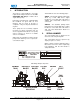
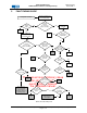
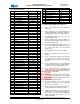
6.2 Pump End Parts List:
Item Description Part No Qty
10 Engine:Hatz 1d90 *E41853B001* 1
11 Stud:M10x60 SY9509097 8
12 Washer:Spring M10 21174-306-927-6 8
13 Nut:Hex Full M10 21882-673-958-3 8
14 Stubshaft 22319 1
15 Capscrew:M8x25 21835-136-977-1 4
16 Washer:Spring M8 21174-305-927-9 4
20 Adaptor:Engine/Pump 22318 1
21 Stud:M10x30 SY9509089 8
22 Washer:Spring M10 21174-306-927-6 8
23 Nut:Hex Full M10 21882-673-958-3 8
24 'O'RING 199.5ID X 3.0 22384.017 1
30 Mech Seal 45 13763 1
31 Washer:Mech Seal 13938 1
32 Circlip: Ext 45 13772 1
40 Wearplate:Back Hsg 22317 1
41 O'RING 219.5ID X 3.0 22385.017 1
50 Mech Seal 45 13763 1
51 Impeller 22321 1
52 Shim:Impeller 1mm 22323 1
53 Shim:Impeller 0.5mm 22324 1
60 Volute 22655 1
61 Stud:M10x30 SY9509089 6
62 Stud:M10x25 SY9509087 6
63 Washer:Spring M10 21174-306-927-6 12
64 Nut:Hex Full M10 21882-673-958-3 12
70 Tee Piece 22320 1
71 Gasket SY5004439 1
72 Gasket SY5004432 1
73 Wear Plate SY3874016 1
74 Stud:M10x30 SY9509089 4
75 Washer:Spring M10 21174-306-927-6 4
76 Nut:Hex Full M10 21882-673-958-3 4
77 Screw:Hex Hd M12x40 21863-222-959-4 2
78 Nut:Hex Full M12 21882-673-958-3 2
80 Valve:Non-Return 22325 1
81 Ball:Nrv (Green) 8075 1
82 Seat:Nrv SY3874014 1
83 Bolt:Hex Hd M12x230 22326 4
90 Assy:Priming Tank SY3802500 1
91 Gasket SY5004373 1
92 Stud:M12x40 SY9509133 8
93 Washer:Spring M12 21174-307-927-3 8
94 Nut:Hex Full M12 21882-675-958-7 8
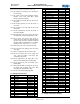
100
110 Adaptor:Male 15533 2
120 Valve:Ball 1/2" Bsp 22416 1
130 Hosetail 12149 1
140 Clip:Hose:18-25mm 5837 1
150 Hose 15446 600
160 Assy:Backprime Line *E41853A007* 1
170 Adaptor:Male 22606 1
180 Valve:Non Return SY3714105 1
Item Description Part No Qty
190 Dipstick 14373 1
200 'O'RING 24.5ID X 3.0 25154-024-716-1 1
210
Elbow:Male Stud
25346
-
221
-
000
-
7
1
220 Clip:'P' Type 14150 1
230 Tube 17341-711-076-4 500
240 Adaptor:Male 22607 1
250
Plug:3/8" Bsp
25221
-
383
-
915
-
0
1
260 Plug:1/4" Bsp 25221-382-915-3 2
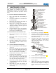
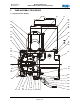
6.3 Pump End Assembly (See section 7.1)
1.1 Refer to the pump end section drawing in
section 7.1
1.2 Place engine (10) on a workbench that is
equipped with lifting equipment suitable to
lift the pump and engine assembly complete.
1.2 Fit eight M10 x 60 studs (11) onto the
engine flywheel casing.
1.3 Fit the stubshaft (14) onto the flywheel on
the engine with four M8 x 25 capscrews (15)
and spring washers (16).
1.4 Place the engine/pump adapter (20) over
the stubshaft and secure using the studs on
the engine with nuts (13) and spring
washers (12).
1.5 Fit eight M10 x 30 studs (21) into adapter.
1.6 Place the 199.5ID ‘O’ ring (24) over the
adapter.
1.7 Fit the secondary mechanical seal stationary
element (30) over the shaft and press it into
the adapter plate ensuring not to damage
the face.
1.8 Fit the rotating element of the mechanical
seal (30) and push it onto the shaft until the
circlip groove is exposed behind the seal.
1.9 Fit the circlip washer (31) followed by the
circlip (32) and ensure the mechanical seal
is securely in place and pulled back against
the circlip.
1.10 Fit the back wearplate (40) over the shaft
and secure using the studs in the adapter
plate with nuts (23) and spring washers (22).
1.11 Fit the remaining ‘O’ ring (41).
1.12 Fit the stationary seat of the primary
mechanical seal (50) over the shaft and
press into the wearplate.
1.13 Fit the rotational part of the mechanical seal
so that it touches the stationary seal face.
1.14 Screw on the impeller (51) (clockwise) and
check the back vane to wear plate clearance
is 0.5-1mm. If it does not fall within this
range, add shims (52 & 53) to give the
required clearance.