AUTOPRIME ACE RANGE CENTRIFUGAL PUMP WORKSHOP MANUAL AUTOPRIME ACE RANGE DIESEL DRIVEN MOBILE PUMPS This manual is a preliminary issue for information only, pending formal issue of the complete manual. SPP Pumps Limited Crucible Close Mushet Industrial Park Coleford Gloucestershire GL16 8PS Telephone: + 44 (0)1594 832 701 Fax: + 44 (0)1594 836 300 Document No: W72-020E Revision No: Preliminary 2 Revision Note No: Date Issued.
Manual No/Rev W72-020E / 1 Workshop Manual for ACE80/100 Diesel Driven Centrifugal Pumps CONTENTS 1. INTRODUCTION...................................................... 3 2. SERIAL NUMBER ................................................... 3 3. SAFETY PRECAUTIONS ........................................ 4 4. 6.1 Safety Symbols ................................................................ 4 6.2 Pump Safety Precautions ................................................. 4 HANDLING & TRANSPORT ...
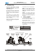
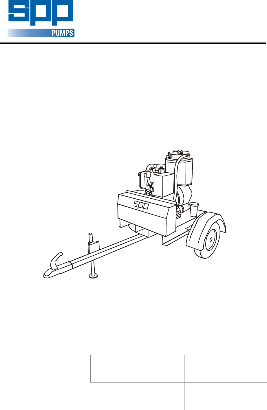
Workshop Manual for ACE80/100 Diesel Driven Centrifugal Pumps 1. Manual No/Rev W72-020E / 1 INTRODUCTION The purpose of this handbook is to provide repair and assembly instructions for the SPP AUTOPRIME ACE Range of mobile diesel engine driven pumps. This Handbook covers the following pumps: ACE80 – An automatic priming mobile pump driven by a Hatz 1D90 diesel engine mounted on a fuel tank and road trailer or skidThis unit is fitted with 3” Bauer hose connections.
Manual No/Rev W72-020E / 1 3. Workshop Manual for ACE80/100 Diesel Driven Centrifugal Pumps SAFETY PRECAUTIONS engines. Be aware of fire risks from items such as exhaust pipes and silencers. Never place flammable items around the unit. 6.1 Safety Symbols Safety instructions within this manual are marked with the following symbols: 2.2.10 This symbol refers to general mechanical aspects of safety. This symbol refers to electrical safety.
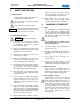
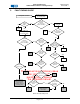
Workshop Manual for ACE80/100 Diesel Driven Centrifugal Pumps 5. Manual No/Rev W72-020E / 1 FAULT FINDING GUIDE Disconnect suction hose Blank off suction entry Fit vacuum gauge Pump Fails to Prime Are all plugs tight? NO Rectify & re-test Reading between 85 - 89 .5 kpa (28.5 0 30 ft H20)? NO Check vertical suction lift YES YES Move Pump Test the Vacuum Pump directly Fit vacuum gauge Lift< or = 8.53m (28ft) for ACE80/100 YES NO Reading between 85 - 89 .5 kpa (28.
Manual No/Rev W72-020E / 1 6. Workshop Manual for ACE80/100 Diesel Driven Centrifugal Pumps MAINTENANCE & REPAIR The extent of disassembly will depend upon the faults identified for rectification from the fault finding guide in section 5.
Workshop Manual for ACE80/100 Diesel Driven Centrifugal Pumps FORCE DEFLECTION RETAINING BOLT LOCKING NUT 6.5 F – Full Pump Stripdown for Overhaul 1. Refer to the pump assembly instructions in section 7. 2. Full pump disassembly for examination of internal clearances or for worn or damaged parts is done generally in the reverse order to pump assembly. 3.
Manual No/Rev W72-020E / 1 7. Workshop Manual for ACE80/100 Diesel Driven Centrifugal Pumps PUMP ASSEMBLY PROCEDURE 6.
Workshop Manual for ACE80/100 Diesel Driven Centrifugal Pumps 6.2 Pump End Parts List: Item 10 11 12 13 14 15 16 20 21 22 23 24 30 31 32 40 41 50 51 52 53 60 61 62 63 64 70 71 72 73 74 75 76 77 78 80 81 82 83 90 91 92 93 94 100 110 120 130 140 150 160 170 180 Description Engine:Hatz 1d90 Stud:M10x60 Washer:Spring M10 Nut:Hex Full M10 Stubshaft Capscrew:M8x25 Washer:Spring M8 Adaptor:Engine/Pump Stud:M10x30 Washer:Spring M10 Nut:Hex Full M10 'O'RING 199.5ID X 3.
Manual No/Rev W72-020E / 1 Workshop Manual for ACE80/100 Diesel Driven Centrifugal Pumps 1.15 Pressure test the mechanical seal assy. 1.16 Fit six M10 x 30 studs (61) onto the back of the volute (60). 1.17 Fit volute over the back wearplate and the impeller and secure with M10 spring washers (63) and nuts (64). ITEM 13 14 15 16 17 1.18 Fit six M10 x 25 studs (62) onto the front of the volute. 18 19 1.19 Fit the large gasket (71) onto the studs on the volute. 20 1.
Workshop Manual for ACE80/100 Diesel Driven Centrifugal Pumps Manual No/Rev W72-020E / 1 This manual is a preliminary issue for information only, pending formal issue of the complete manual.
Manual No/Rev W72-020E / 1 Workshop Manual for ACE80/100 Diesel Driven Centrifugal Pumps 6.6 Priming Tank Assembly NOTE: When the lifting point bracket is fitted remove the lifter from the engine. Turn the lifter over and fit it upside down so it isn’t used to lift the whole unit when complete. 1.1 Refer to priming tank section drawing in section 7.5. 1.2 If tank is new, fit all studs in the positions indicated on the section drawing. 1.3 Fit the drain plug (43) with the washer (34). 4.3.
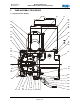
Workshop Manual for ACE80/100 Diesel Driven Centrifugal Pumps 4.7 Manual No/Rev W72-020E / 1 Fit pump/engine assy. to chassis using two M12 x 40 bolts for the pump three M12 x 35 bolts for the engine feet. (See Figure 4) Figure 6 4.10 Fit back prime. (See sectional drawing parts 150, 160, 170 and 230) Figure 4 4.8 Wire up engine and fit engine switch and hour meter using the switch bracket. (See photo and wiring diagram (Figures 6 &7). 4.9 Fit fuel filter and fuel lines. (Figure 5) 4.9.
Manual No/Rev W72-020E / 1 Workshop Manual for ACE80/100 Diesel Driven Centrifugal Pumps 4.17 Fit vac pump and bleed filter with four M8 flanged bolts. (Figure 8) 4.18 Fit taper locks and pulleys to vac pump and engine. (Figure 9) 4.19 Fit belt over the pulleys, fit the tensioner with two M8 bolts, tension belt and mark bolt heads on tensioner. (Figure 9) 4.20 Fit vac pump exhaust system and inlet pipe work. (Figure 8) 4.20.1 Fit reducing bush and hose tail together and fit bush to vac pump casing 4.20.
Workshop Manual for ACE80/100 Diesel Driven Centrifugal Pumps Manual No/Rev W72-020E / 1 5.4.3 Fit angle bracket onto the chassis with two M12 x 30 flanged bolts and flanged nuts. 5.4.4 Fit clamp onto bracket with two M12 x 30 flanged bolts andflanged nuts 6.9 Final preparation 6.1 Test unit. 5.4.5 Place rear leg into clamp and tighten. 6.2 PDI unit. 5.4.6 Bolt two lighting board brackets onto back of chassis using two M6 x 10 flanged bolts and two flanged nuts per bracket. 6.
Manual No/Rev W72-020E / 1 Workshop Manual for ACE80/100 Diesel Driven Centrifugal Pumps 9. 6.
Workshop Manual for ACE80/100 Diesel Driven Centrifugal Pumps ITEM 1 2 3 4 5 6 7 8 9 10 DESCRIPTION Battery box Battery box lid Battery clamp Screw: M12 x 35 Washer: M12 Washer: spring M12 Nut: M12 Battery mat Battery: 12v Screw: M8 x 16 PART No 13165 13166 12483 21863-220-347-0 SY9509680 SY9509808 SY9509654 SY3874047 SY7004404 21863-132-347-6 QTY ITEM 1 1 2 2 2 2 2 1 1 2 11 12 13 14 15 16 17 18 19 DESCRIPTION Washer: spring M8 Washer: M8 Lead: battery +ve Lead: battery -ve Screw: M8 x 20 Nut: M8 Sc
Manual No/Rev W72-020E / 1 Workshop Manual for ACE80/100 Diesel Driven Centrifugal Pumps 6.2 BAUER FITTINGS 9.1 ITEM 1 2 3 4 5 6 9.1 ITEM 1 2 3 4 5 6 9.1 80-18 DESCRIPTION 3" Bauer male/4" flange Nut: M16 Washer: spring M16 Gasket Bolt: M16 x 55 3" Bauer female/ 4" flange, includes 3" Sealing ring PART No QTY ITEM 7 13502 1 SY9509656 SY9509810 SY5004418 21867-315-959-9 8 8 2 8 13503 1 SY3194288 1 DESCRIPTION 3" Split intake assy.
Workshop Manual for ACE80/100 Diesel Driven Centrifugal Pumps 9.2 Manual No/Rev W72-020E / 1 WIRING DIAGRAM This manual is a preliminary issue for information only, pending formal issue of the complete manual.
Manual No/Rev W72-020E / 1 Workshop Manual for ACE80/100 Diesel Driven Centrifugal Pumps Our policy is one of continuous improvement and we reserve the right to alter specifications at any time Page 20 of 21
Workshop Manual for ACE80/100 Diesel Driven Centrifugal Pumps 10. Manual No/Rev W72-020E / 1 SPARES & SERVICE SPP Pumps Limited operate a comprehensive Spares and Service support network throughout the world, and can be contacted as follows SPARES & SERVICE Telephone +44 (0)118 932 3123 For spare parts, supply only. For breakdowns, spare parts and, on-site fitting, pump installation and, commissioning, and service contracts.