SPIRE III Series Laminator Models 44T, 64T, 64Ct, INSTALLATION & OPERATION MANUAL Document Number: 1723267 Rev. A Do not duplicate without written permission from ACCO Brands.
SPIRE III Series – Installation and Operating Instructions ACCO Brands reserves the right to make changes to this publication and to the products described in it without notice. All specifications and information concerning products are subject to change without notice.
SPIRE III Series – Installation and Operating Instructions Table of Contents Introduction.................................................................. i Features................................................................... i Applications............................................................. i Films......................................................................... i 1. Safety Cautions...................................................................1-2 General.....................
SPIRE III Series – Installation and Operating Instructions Film Alignment........................................................6-13 Film Tension...........................................................6-13 Testing the Web.................................................6-13 Lamination Guide ..................................................6-13 7. Operator Maintenance Caring for the SPIRE Series Laminator....................7-1 Cleaning The Rollers............................................
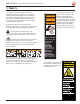
SPIRE III Series – Installation and Operating Instructions 1. Safety Your safety, as well as the safety of others is important. Before you install or use the machine, read and follow all the safety notices carefully in this chapter. In this instruction manual, and on the laminator, you will find important safety notices related to the use of the laminator. Observe all the safety information provided. WARNING ATTENTION MUCHO CUIDADO Read all of the instructions and save these instructions for further use.
SPIRE III Series – Installation and Operating Instructions This safety notice means that your fingers and hands could be trapped and crushed in the rollers. Clothing, jewelry and long hair could be caught in the rollers and pull you into them. Keep fingers, hands clothing, jewelry, and long hair away from the rollers. WARNING MUCHO CUIDADO ATTENTION WARNUNG CRUSH HAZARD Keep hands and clothing away from rollers. RISQUE DE BROYEMENT. Tenir mains et vêtements a l'écart RIESGO DE PINCHAMIENTO.
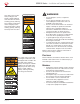
SPIRE III Series – Installation and Operating Instructions Before you operate this machine, it is important that you read and understand the entire contents of these instructions and be fully trained. CAUTION: The receptacle must be located near the equipment and must be easily accessible. Disconnect the attachment plug from the receptacle to which it is connected and keep the power supply cord in your possession while moving the laminator.
SPIRE III Series – Installation and Operating Instructions Safety Label Locations Inside electrical panel on back WARNING MUCHO CUIDADO ATTENTION WARNUNG CRUSH HAZARD Keep hands and clothing away from rollers. RISQUE DE BROYEMENT. Tenir mains et vêtements a l'écart Both rear sides On back RIESGO DE PINCHAMIENTO. Mantener las manos y prendas de vestir a distancia. WARNING QUETSCHGEFAHR. Hände und Kleidung fernhalten. ATTENTION MUCHO CUIDADO HOT ROLLERS. CRUSH HAZARD. Keep hands and fingers away.
SPIRE III Series – Installation and Operating Instructions 2. Warranty Limited 90-Day Warranty ACCO Brands USA LLC, ACCO Brands, 4 Corporate Drive, Lake Zurich, IL 60047 (in Canada, ACCO Brands Canada Inc., 7381 Bramalea Road, Mississauga ON L5S1C4; and in Mexico, ACCO Brands Mexicana,Neptuno 43, Fraccionamiento Nueva Industrial Vallejo México 07700 D.F.
SPIRE III Series – Installation and Operating Instructions Page 2-2
SPIRE III Series – Installation and Operating Instructions 3. Specifications Model 44T 64T Operating Speed Up to 20 fpm (6 mpm) Maximum Temperature 300 °F (149 °C) Maximum Mounting Thickness Main Roller: 2 in. (50 mm) Max. Pull Roller: 2 in. (50 mm) total working gap Maximum Film Width Dimensions (unit only) • Width • Height • Depth Weight • Unit only • Shipping Electrical Requirements (U.S. Models) • Voltage • Current • U.S. Receptacle 64Ct 120 °F (49 °C) Main Roller: 2 in. (50 mm) Max. 44 in.
SPIRE III Series – Installation and Operating Instructions FCC Class A Notice Modifications This device complies with Part 15 of the FCC Rules. Operation is subject to the following two conditions: Any modifications made to this device that are not approved by ACCO Brands may void the authority granted to the user by the FCC and/or by Industry Canada to operate this equipment. • This device may not cause harmful interference.
SPIRE III Series – Installation and Operating Instructions 4. Installation WARNING: Do not attempt to service or repair the laminator. Failure to observe this warning could result in severe personal injury or death. Disconnect the plug from the receptacle and contact GBC Technical Service when one or more of the following has occurred. • • • • The power supply cord or attachment plug is damaged. Liquid has been spilled into the laminator. The laminator is malfunctioning.
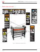
SPIRE III Series – Installation and Operating Instructions Location Provide adequate space around the laminator as shown in the illustration. The laminator should be located so that exiting film drops freely to the floor or to a table that is lower than the exit point of the laminator. Accumulation of laminate immediately behind the laminator as it exits the equipment may cause the film to wrap around the rollers, jamming the machine. Avoid locating the laminator near sources of heat or cold.
SPIRE III Series – Installation and Operating Instructions 5. Feature Guide This chapter helps you identify the main components of the laminator. Note: Depending on the model of your Laminator and its version, the photos in this guide may not look like your Laminator. However, the components and functions are the same. Your laminator may not have all the options shown below. For option upgrades, contact your local sales rep or Technical support. Refer to”GBC Technical Service”.
SPIRE III Series – Installation and Operating Instructions Emergency Stop Switches To disengage the Emergency Stop Switch, turn it clockwise after the emergency condition has been resolved. Figure 6. Emergency Stop Switch on back of the laminator. Figure 5. Emergency Stop Switch near Operator Panel. Four Emergency Stop, (also referred to as E-Stop) Switches Switches are available on the Laminator. The Emergency Stop Switches are located on all four upper corners of the machine.
SPIRE III Series – Installation and Operating Instructions B. Upper Unwind Shaft C. Upper Idler The Upper Unwind Shaft is used to hold film or media that will be used for the job, and to apply brake tension. The Upper Idler guides the upper lamination onto the Top Main Roller, ensuring a constant amount of wrap on the Top Main Roller. Main Rollers and Upper Idler Gap/Pressure Crank Figure 8. Top and bottom Main Rollers, and Upper Idler.
SPIRE III Series – Installation and Operating Instructions Footswitch C. Lower Idler Bar The Lower Idler guides the lower film or media onto the Bottom Main Roller, ensuring a constant amount of wrap is on the Bottom Main Roller. Multi Core Adaptors Multi Core Adaptors grip the media supply tube. The Multi Core Adaptors accommodate 2 through 3 inch diameter cores. Figure 10. Footswitch. The Footswitch allows you to start and stop the laminator while handling the item to be laminated.
SPIRE III Series – Installation and Operating Instructions Shaft Storage Cradle Emergency Stop Switches The Emergency Stop Switches are located on all four upper corners of the machine. Pull Rollers raise and lower with the Main Rollers by turning the Gap/Pressure Crank. A Pull Rollers (44T, 64T) The Pull Rollers are motor driven and are located at the back of the laminator. The rollers pull the film and image through the laminator. C.
SPIRE III Series – Installation and Operating Instructions Rear Table and Optional Idler Figure 16. Rear Table and Optional Idler. A. Rear Table The Rear Table supports the media as it exits the machine. B. Optional Rear Table Idler The Optional Rear Table Idler is part of the Rear Table and assists the web as it exits the laminator. Photo Safety Sensor, Gap Gauge, Table Alignment Knob A.
SPIRE III Series – Installation and Operating Instructions Removing the Pressure Plate To remove the Pressure Plate: 1. Feed Table To unlock the Pressure Plate Lock, press the Release button. The Lock releases the locking pin from the hole. Figure 21. Feed Table and optional Idler. Figure 19. Pressure Plate Release button and locking pin. The Feed Table (A) is used to position items for laminating and mounting. The Feed Table is raised only when you load film and to clean the rollers.
SPIRE III Series – Installation and Operating Instructions 3. Raise it until it is above the Front Main Roller. IR Sensor Figure 25. IR Sensor Behind the Top Main Roller. Figure 23. Feed Table in Raised Position. 4. Secure the Feed Table with an Upper Front Rewind Shaft Clevis Pin. Depending on the laminator, IR Sensors read the temperature of the heated Main Rollers to ensure proper temperature. The Top Main Roller (44T, 64T, 64Ct) IR Sensor is located behind the Main Roller.
SPIRE III Series – Installation and Operating Instructions Tension Adjustment Knobs C. Upper Front Rewind Tension Turn the knobs clockwise to increase tension and counterclockwise to reduce tension. Use the Upper Front Rewind Tension knob to adjust the amount of pull on the release liner. This prevents the release liner from being pulled into the laminator or the film from wrapping around the rewind tube. D.
SPIRE III Series – Installation and Operating Instructions Control Panel D. FAN (44T, 64T) The Control Panel is located on the right side of the machine and controls all operations of the machine. Press to turn on the fans and press again to turn off the fans. The Fans only run when the motor is rotating. When FAN is pressed, the LED turns on, but the fans only function when the motor is rotating. When the motor stops rotating, the fans also stop. E.
SPIRE III Series – Installation and Operating Instructions A. Roller Heater Temperature Display A. Lower Roller Heater Temperature Display Displays the lower heater setpoint temperature. If the Lower IR sensor is blocked, the alarm sounds and the display flashes until the obstruction is resolved and the MEASURE button is pressed. Refer to “IR Sensor” and “Clear a Film Jam (Wrap-Up)” sections. Displays the lower heater setpoint temperature.
SPIRE III Series – Installation and Operating Instructions Power To apply power to the laminator, flip the Breaker up to the ON position. To disconnect power to the laminator, flip the Breaker to the OFF position. If the Breaker has tripped, correct the problem that caused it to trip and then press the orange Rest button to reset the breaker. To test the Breaker, press the blue Test button. Press the Rest button to reset the breaker. Castors Figure 30. Power Cord (44T, 64T).
SPIRE III Series – Installation and Operating Instructions 6. Operation Sequence of Operation Mode RUN When machine is running Photo Safety Sensor Clear and No Micro Switches activated Photo Safety Sensor Blocked Micro-Switch Activated Emergency Stop (E-Stop) Switch Pressed When RUN is pressed, the rollers rotate at the set speed. When the Photo Safety Sensor is blocked, the rollers do not rotate when RUN is pressed.
SPIRE III Series – Installation and Operating Instructions Loading Film The SPIRE Series laminator runs poly-in and poly-out pressure sensitive adhesive (PSA) films. Poly-in means the adhesive side of the film is on the inside of the film roll. Poly-out means the adhesive is on the outside of the film roll. IMPORTANT: The top and Lower rolls of laminating film must be the same width. Always change the top and Lower supply rolls at the same time.
SPIRE III Series – Installation and Operating Instructions Webbing the Machine Prior to webbing the machine, ensure the supply rolls are centered on the shafts. Also make sure to remove all brake tension on the unwind and supply shafts before you begin. Warning: Rollers may be hot. Hot rollers could burn you. Take care not to touch rollers while removing, loading, or changing film. Caution: Press STOP to ensure the machine is not running. Figure 35. Shaft slot indicator. 3.
SPIRE III Series – Installation and Operating Instructions 6. Remove the Pressure Plate. Refer to the “Removing the Pressure Plate” section. 7. Raise the Feed Table. Refer to the “Raising the Feed Table” section. WARNING: Raising the Feed Table exposes moving parts. This means you can be harmed when the Feed Table is raised. Make sure to lower the Feed Table when film loading is completed. 8. For the Lower media, guide the media around the idler and up to the Main Rollers. Figure 38.
SPIRE III Series – Installation and Operating Instructions WARNING: Raising the Feed Table exposes moving parts. This means you can be harmed when the Feed Table is raised. Make sure to lower the Feed Table when film loading is completed. TABLE IN RAISED POSITION REWINDER PSA LAMINATE Figure 43. Pressing a threading card into the nip. (1) 13. Press the Footswitch and guide the film to the Main Rollers. IDLER 14. Adjust the Rewinder tension so that the release liner does not pull into the nip area.
SPIRE III Series – Installation and Operating Instructions 10. Attach the film to the existing web on the Main Rollers. Make sure to carefully align the edges of the films before tacking them together. REWINDER PSA LAMINATE To remove the web: 1. Press STOP. 2. Remove the Pressure Plate. Refer to the “Removing the Pressure Plate” section. 3. Raise the Feed Table. Refer to the “Raising the Feed Table” section.
SPIRE III Series – Installation and Operating Instructions 8. Carefully grab the web (top and bottom film), from the front operating position and pull towards you. REWINDER PSA LAMINATE Clear a Film Jam (Wrap-Up) Film jams (wrap-ups) may occur if the film is loaded backwards or if the area at which film exits the equipment is blocked. The film can wrap around the Main or Pull Rollers during webbing if a threading card is not used. To clear a jam (wrap-up): IDLER PULL WEB 1.
SPIRE III Series – Installation and Operating Instructions Precoating Mount Boards Tips • • Use this process to precoat the front of substrates with pressure-sensitive adhesive (PSA). Precoated boards are useful for mounting graphics that will not be laminated. Examples include photographs, POP signage, and presentations. NOTE: In the following illustration, depending on the laminator model, you may or may not have Pull rollers and the Feed Table either pivots or is removable.
SPIRE III Series – Installation and Operating Instructions 3. Refer to “Pressure Sensitive Mounting - Decal Front” for step-by-step instructions. Tips • • • • • When taping film liner to the Rewind Tube, use only one piece of tape to allow the film to shift if necessary and it is easier to remove the liner later. When webbing the top laminate, make sure the edges of the laminate line up from the unwind to the laminate roller to ensure the materials feed straight.
SPIRE III Series – Installation and Operating Instructions 9. Press the Footswitch. 10. As the materials feed into the rollers, pull the release liner off the decal. 11. Continue until the decal and substrate exits the rollers. • • Use this process to mount a graphic to a precoated substrate. Examples include POP signage, legal graphics, photographs, and presentations.
SPIRE III Series – Installation and Operating Instructions 9. Press the Footswitch. 10. As the materials feed into the rollers, pull the release liner off the substrate. Thermal Lamination Use this process to encapsulate images between two thermal films. 11. Continue until the graphic and substrate exits the rollers. Examples include menus, posters, and photos. Tips NOTE: In the following illustration, Pull rollers are required.
SPIRE III Series – Installation and Operating Instructions 11. Press a threading card into the nip of the Main Rollers, pushing the laminates into the nip. 12. Press Run and guide the laminates to the Main Rollers. 3. 4. Tips for Custom Application #2 13. After the threading card exits the Main Rollers, lower the rollers, and adjust the film tension as needed. 14. Press STOP and check the quality of the lamination. Main Roller 15. Press Run and proceed with the lamination.
SPIRE III Series – Installation and Operating Instructions Film Alignment Testing the Web The top and bottom supply rolls must be aligned as closely as possible. Misalignment can cause adhesives to stick to the rollers. The 3 inch Extruded AUTOGRIP Shafts have rulers incorporated to assist centering the film on the shafts. After webbing the machine, it is important that the films run straight and evenly. To test the web: 1. Set the Roller Pressure Crank to an appropriate gap. 2.
SPIRE III Series – Installation and Operating Instructions Page 6-14
SPIRE III Series – Installation and Operating Instructions 7. Operator Maintenance Caring for the SPIRE Series Laminator The only maintenance required by the operator is to periodically clean the rollers. The following procedure will help keep the rollers free of dirt and adhesive, which has been deposited along the edge of the laminating film. Proper alignment of the rolls of film reduces the amount of adhesive on the rollers.
SPIRE III Series – Installation and Operating Instructions Troubleshooting Symptom Possible Cause Corrective Action LCD does not illuminate Laminator not connected to electrical on the control panel when supply. the ON/OFF switch is in the ON position. Blown fuse. Insert attachment plug into receptacle. Rollers do not turn. Photo Safety Sensors blocked. Unblock Photo Safety Sensors. Feed Table Interlock Latch not in place. Reseat Interlock Latch all the way down until the micro switch activates.
SPIRE III Series – Installation and Operating Instructions WEEE Statement At the end of its useful life, your product is considered to be Waste Electrical and Electronic Equipment (WEEE). As such, it is important to note that: • • • • • • • WEEE is not to be disposed of as unsorted municipal waste. It is to be collected separately such that it can be disassembled so its components and materials can be recycled, re-used, and recovered (burned for energy content in electricity production).
SPIRE III Series – Installation and Operating Instructions Glossary of Terms The terms listed here appear in this manual or are commonly used in the normal use of laminators. Term Definition Decal Media that has an overlaminate on the front and a mount adhesive on the back. Film Adhesive material that is applied to a substrate or media. Gap The space between two rollers. In-feed The side of the laminator where media is fed into the machine to be laminated.
SPIRE III Series – Installation and Operating Instructions Notes Date Note Page 7-5
SPIRE III Series – Installation and Operating Instructions Page 7-6
SPIRE III Series – Installation and Operating Instructions Page 7-7
ACCO Brands 4 Corporate Drive Lake Zurich, IL 60047 In USA call 800.772.9281 www.gbcconnect.com ACCO Brands Canada 5 Precidio Court Brampton, ON L6S-6B7 800.263.1063 www.gbccanada.com ACCO Mexicana Neptuno #43, Colonia Nueva Industrial Vallejo Delagacion Gustavo A. Madero, CP 07700 México, DF. (55) 1500-5578 www.gbc.com.mx © 2013 ACCO Brands. All rights reserved. ACCO® is a registered trademark of ACCO Brands. GBC® is a registered trademark of General Binding Corporation. 1723267 Rev.