Patient Programmer Model MN0600 User Manual Spinal Modulation, Inc. 1135 O’Brien Drive Menlo Park, CA 94025 USA CAUTION – Investigational Device Limited by Federal (US) Law to Investigational Use Copyright © June 2011 by Spinal Modulation, Inc. All Rights Reserved.
SPINAL MODULATION, INC. PATIENT PROGRAMMER USER MANUAL TABLE OF CONTENTS EXPLANATION OF SYMBOLS ON PRODUCT OR PACKAGE LABELING ....................................................................... 3 GLOSSARY .............................................................................................................................................. 4 INTRODUCTION ........................................................................................................................................
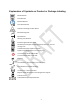
Explanation of Symbols on Product or Package Labeling Model Number Serial Number Read the Manual Consult the Manual Contents of Package are Non‐Sterile Manufacturing Date Manufacturer Warning. Pay attention. Protected against Electric Shock Not waterproof. Applies to the Programmer when it is not in its carrying case. Limited waterproof. Applies to the TNS. Applies to the Programmer in its carrying case. Turns the Programmer ON and OFF. Turns stimulation OFF on the TNS.
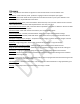
Glossary Lead – Surgical wire: takes electrical signals from the neurostimulator to the stimulation area. Stimulation – Small electrical pulses: produces a tingling sensation and replaces pain signals. Stimulator –Device that makes electrical pulses that stimulate the nerves in your spine: defined as Trial Neurostimulator or Implantable Neurostimulator.
INTRODUCTION Your Patient Programmer is used to program your stimulator device, if required. This User Manual gives detailed instructions on how to safely use your Patient Programmer and your stimulator device. It also instructs you on how to recharge your Patient Programmer. See your doctor if you have any questions.
Warnings (continued) • Strong electromagnetic fields may interfere with the stimulator device. This interference can affect the stimulation level and cause discomfort. Avoid theft detection devices at store and library exits. Also avoid airport security screeners. Do not stand near the screening equipment. • Other equipment that may cause interference includes but is not limited to: power generators, arc welders and large magnetized speakers. Do not stand near these devices.
Device Precautions (continued) • Failure of your stimulator system, although unlikely, is possible due to random component failure. If any part of your stimulator system stops working or you see a change in how it works, discontinue use and contact your doctor during normal business hours. • Return your Patient Programmer and TNS device to your doctor at the end of the trial period. Do not discard or burn the Patient Programmer or TNS device. Fire may cause the internal batteries to explode.
Therapy Precautions (continued) • Tell your regular doctor(s) or healthcare providers that you have a stimulator device. Do not undergo any elective medical procedures without first discussing them with your physician. Some medical devices or therapies, such as those listed below, may interfere with your stimulator device: o Electrocautery – Electric probe to cauterize blood vessels and stop bleeding during surgery. o Lithotripsy – Shock waves to break up gallstones and kidney stones.
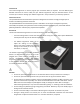
PATIENT PROGRAMMER OVERVIEW Your Patient Programmer is a portable, handheld device. It is powered by an internal, rechargeable battery. It can also be plugged into a power outlet. Your Patient Programmer works with your stimulator device to control stimulation. Your doctor will explain how to use the Patient Programmer to adjust stimulation for optimal pain relief. Keep your Patient Programmer near you at all times. This allows you to adjust stimulation, if necessary.
PATIENT PROGRAMMER FEATURES With your Patient Programmer, you can: • Turn OFF all stimulation, if required. • Turn stimulation ON or OFF for each body region. • Adjust the stimulation level for each body region. • Change the Group for stimulation. See “Select Group” under the “Pain Control Screen” section. • View your stimulator device ID information. • View your name or your ID number. • View your lead implant date. • View your physician name, clinic name and contact information.
NOTE: If the Patient Programmer does not turn ON, charge the battery, and try again.
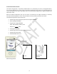
MAIN MENU The Programmer Main Menu displays two main functions: • Connect: Allows you to connect to your stimulator device; also allows you to adjust stimulation settings. • Programmer Setup: Allows you to set your Patient Programmer date and time; also allows you to view information about your stimulator device. The Main Menu identifies the device as your Spinal Modulation Patient Programmer. Your physician, clinic and the clinic phone number are also shown.
Stimulator Device Binding Your doctor will bind your stimulator device to your Patient Programmer. You cannot edit this information. Connect Press the “Connect” button on the Main Menu to connect to your stimulator device. Once connected, you can adjust stimulation settings. See the “Connecting to Your Stimulator Device” section below for more detail. Magnet A magnet is located under the magnet symbol on the back side of the Patient Programmer.
to confirm that your Patient Programmer is near enough to the stimulator device. After confirming that your Patient Programmer is within 6 feet of the stimulator device, press “OK”. Press “Connect” again.
PAIN CONTROL SCREEN At the top of the Pain Control screen. The ID Heading shows your name or ID number and your stimulator device’s serial number. The “Turn All Stimulation OFF” button is below the ID Heading. Two tabs are below the “Turn All Stimulation OFF” button: the “Pain Control” tab and the “Info” (Information) tab. See the “Adjusting Your Stimulator Device Settings” section in this User Manual for more detail. The “Exit” button at the bottom right side of the screen returns you to the Main Menu.
PROGRAMMER STATUS BAR The Programmer Status Bar is located at the bottom of the Patient Programmer screen. The status bar shows the Programmer‐stimulator connection status, the battery charge level and the time.
PAIN CONTROL TAB Select the “Pain Control” tab located at the top of the Pain Control screen. From the “Pain Control” tab, you can turn stimulation ON or OFF for each body region. You can also adjust the stimulation level for each body region. TURN STIMULATION ON OR OFF FOR A BODY REGION Your Patient Programmer shows the names of one to four body regions in which your leads have been placed. To turn stimulation ON or OFF for a body region: • Select the body region by pressing the desired tab.
INFO TAB The “Info” (Information) tab contains three tabs, the “Device” tab, the “Physician” tab, and the “Clinic” tab. DEVICE TAB AND PHYSICIAN TAB The “Device” tab and “Physician” tab show the following information: Stimulator Voltage Information NOTE: INS battery information (does not pertain to external TNS device). Stimulator Identification Information • Stimulator Device Firmware Version. • Date INS device was implanted (does not pertain to external TNS device).
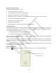
USING YOUR TNS DEVICE To connect your Programmer to your TNS, push the “Connect” button on the Patient Programmer. Move the Patient Programmer magnet over the TNS in a circular motion. This will allow you to adjust stimulation settings using the Patient Programmer. To quickly turn stimulation off, press the red button on the TNS for more than 2 seconds or push the “Turn all Stimulation OFF” button on the Programmer screen.
GUIDANCE AND MANUFACTURER’S DECLARATION ELECTROMAGNETIC EMISSIONS The Spinal Modulation Neurostimulator System is intended for use in the electromagnetic environment specified below. The customer or the user of the Spinal Modulation Neurostimulator System should assure that it is used in such an environment.
Guidance and Manufacturer’s Declaration ELECTROMAGNETIC IMMUNITY The Spinal Modulation Neurostimulator System is intended for use in the electromagnetic environment specified below. The customer or the user of the Spinal Modulation Neurostimulator System should assure that it is used in such an environment.
Guidance and Manufacturer’s Declaration ELECTROMAGNETIC IMMUNITY The Spinal Modulation Neurostimulation System is intended for use in the electromagnetic environment specified below.
Appendix I: INS Battery Life The following four tables estimate INS battery life under the given load impedance conditions. Tables 1 through 4 list estimated longevity based on 1‐lead stimulation, active 24 hours a day.
Table 1: Load Impedance = 600 ohms All longevity values are in months Pulsewidth Amplitude Frequency 40uS 100uS 200uS 300uS 400uS 500uS 600uS 700uS 720uS 0.1mA 0.2mA 0.4mA 0.6mA 0.8mA 4Hz 20Hz 40Hz 60Hz 80Hz 100Hz 4Hz 20Hz 40Hz 60Hz 80Hz 100Hz 4Hz 20Hz 40Hz 60Hz 80Hz 100Hz 4Hz 20Hz 40Hz 60Hz 80Hz 100Hz 4Hz 20Hz 40Hz 60Hz 80Hz 100Hz 83.9 81.5 78.6 76.0 73.5 71.2 83.8 81.1 78.0 75.1 72.4 69.8 83.7 80.4 76.7 73.3 70.1 67.3 83.5 79.7 75.4 71.5 68.1 64.9 83.4 79.0 74.2 69.9 66.1 62.7 83.8 80.9 77.6 74.
Table 1: Load Impedance = 600 ohms (Continued) All longevity values are in months Pulsewidth 40uS 100uS 200uS 300uS 400uS 500uS 600uS 700uS 720uS 1.0mA 1.5mA 2.0mA 4.0mA 6.0mA 4Hz 20Hz 40Hz 60Hz 80Hz 100Hz 4Hz 20Hz 40Hz 60Hz 80Hz 100Hz 4Hz 20Hz 40Hz 60Hz 80Hz 100Hz 4Hz 20Hz 40Hz 60Hz 80Hz 100Hz 4Hz 20Hz 40Hz 60Hz 80Hz 100Hz 83.2 78.3 73.0 68.3 64.2 60.6 82.8 76.7 70.2 64.7 60.0 56.0 82.5 75.1 67.6 61.5 56.4 52.0 56.6 46.3 37.7 31.8 27.5 24.3 52.6 35.3 25.0 19.4 15.8 13.3 82.1 73.6 65.2 58.5 53.1 48.
Table 2: Load Impedance = 1 Kohm All longevity values are in months Pulsewidth Amplitude Frequency 40uS 100uS 200uS 300uS 400uS 500uS 600uS 700uS 720uS 0.1mA 0.2mA 0.4mA 0.6mA 0.8mA 4Hz 20Hz 40Hz 60Hz 80Hz 100Hz 4Hz 20Hz 40Hz 60Hz 80Hz 100Hz 4Hz 20Hz 40Hz 60Hz 80Hz 100Hz 4Hz 20Hz 40Hz 60Hz 80Hz 100Hz 4Hz 20Hz 40Hz 60Hz 80Hz 100Hz 83.9 81.5 78.6 76.0 73.5 71.2 83.8 81.1 78.0 75.1 72.4 69.8 83.7 80.4 76.7 73.3 70.1 67.3 83.5 79.7 75.4 71.5 68.1 64.9 83.4 79.0 74.2 69.9 66.1 62.7 83.8 80.9 77.6 74.6 71.
Table 2: Load Impedance = 1 Kohm (Continued) All longevity values are in months Pulsewidth 40uS 100uS 200uS 300uS 400uS 500uS 600uS 700uS 720uS 1.0mA 1.5mA 2.0mA 4.0mA 6.0mA 4Hz 20Hz 40Hz 60Hz 80Hz 100Hz 4Hz 20Hz 40Hz 60Hz 80Hz 100Hz 4Hz 20Hz 40Hz 60Hz 80Hz 100Hz 4Hz 20Hz 40Hz 60Hz 80Hz 100Hz 4Hz 20Hz 40Hz 60Hz 80Hz 100Hz 83.2 78.3 73.0 68.3 64.2 60.6 82.8 76.7 70.2 64.7 60.0 56.0 58.4 53.1 47.7 43.2 39.6 36.5 53.0 36.3 26.1 20.3 16.7 14.1 51.4 32.7 22.4 17.1 13.8 11.6 82.1 73.6 65.2 58.5 53.1 48.
Table 3: Load Impedance = 1.5 Kohm All longevity values are in months Pulsewidth Amplitude Frequency 40uS 100uS 200uS 300uS 400uS 500uS 600uS 700uS 720uS 0.1mA 0.2mA 0.4mA 0.6mA 0.8mA 4Hz 20Hz 40Hz 60Hz 80Hz 100Hz 4Hz 20Hz 40Hz 60Hz 80Hz 100Hz 4Hz 20Hz 40Hz 60Hz 80Hz 100Hz 4Hz 20Hz 40Hz 60Hz 80Hz 100Hz 4Hz 20Hz 40Hz 60Hz 80Hz 100Hz 83.9 81.5 78.6 76.0 73.5 71.2 83.8 81.1 78.0 75.1 72.4 69.8 83.7 80.4 76.7 73.3 70.1 67.3 83.5 79.7 75.4 71.5 68.1 64.9 83.4 79.0 74.2 69.9 66.1 62.7 83.8 80.9 77.6 74.
Table 3: Load Impedance = 1.5 Kohm (Continued) All longevity values are in months Pulsewidth 40uS 100uS 200uS 300uS 400uS 500uS 600uS 700uS 720uS 1.0mA 1.5mA 2.0mA 4.0mA 6.0mA 4Hz 20Hz 40Hz 60Hz 80Hz 100Hz 4Hz 20Hz 40Hz 60Hz 80Hz 100Hz 4Hz 20Hz 40Hz 60Hz 80Hz 100Hz 4Hz 20Hz 40Hz 60Hz 80Hz 100Hz 4Hz 20Hz 40Hz 60Hz 80Hz 100Hz 83.2 78.3 73.0 68.3 64.2 60.6 58.2 52.0 45.9 41.1 37.2 33.9 56.4 45.7 36.9 30.9 26.6 23.4 52.6 35.3 25.0 19.3 15.8 13.3 52.6 35.3 25.0 19.3 15.8 13.3 82.1 73.6 65.2 58.5 53.1 48.
Table 4: Load Impedance = 2 Kohm All longevity values are in months Pulsewidth Amplitude Frequency 40uS 100uS 200uS 300uS 400uS 500uS 600uS 700uS 720uS 0.1mA 0.2mA 0.4mA 0.6mA 0.8mA 4Hz 20Hz 40Hz 60Hz 80Hz 100Hz 4Hz 20Hz 40Hz 60Hz 80Hz 100Hz 4Hz 20Hz 40Hz 60Hz 80Hz 100Hz 4Hz 20Hz 40Hz 60Hz 80Hz 100Hz 4Hz 20Hz 40Hz 60Hz 80Hz 100Hz 83.9 81.5 78.6 76.0 73.5 71.2 83.8 81.1 78.0 75.1 72.4 69.8 83.7 80.4 76.7 73.3 70.1 67.3 83.5 79.7 75.4 71.5 68.1 64.9 83.4 79.0 74.2 69.9 66.1 62.7 83.8 80.9 77.6 74.6 71.
Table 4: Load Impedance = 2 Kohm (Continued) All longevity values are in months Pulsewidth 40uS 100uS 200uS 300uS 400uS 500uS 600uS 700uS 720uS 1.0mA 1.5mA 2.0mA 4.0mA 6.0mA 4Hz 20Hz 40Hz 60Hz 80Hz 100Hz 4Hz 20Hz 40Hz 60Hz 80Hz 100Hz 4Hz 20Hz 40Hz 60Hz 80Hz 100Hz 4Hz 20Hz 40Hz 60Hz 80Hz 100Hz 4Hz 20Hz 40Hz 60Hz 80Hz 100Hz 58.9 55.0 50.7 47.1 44.0 41.2 56.7 46.7 38.2 32.4 28.1 24.8 54.5 40.1 30.1 24.1 20.1 17.2 53.2 36.7 26.5 20.7 17.0 14.4 53.2 36.7 26.5 20.7 17.0 14.4 58.2 52.2 46.3 41.5 37.7 34.
Appendix II: Troubleshooting Pop Up Message Possible Solution Connection with your stimulator was lost. Please reconnect. • Swipe the programmer over the stimulator to establish connection and reconnect to the device. • If you still cannot connect, move the programmer closer to the stimulator. Continue to swipe the magnet over the stimulator. • Move to another location; there may be interference in your current location. • Press “OK” and attempt to reconnect to the stimulator.