Clinical Programmer Model MN0700 User Manual Spinal Modulation, Inc. 1135 O’Brien Drive Menlo Park, CA 94025 USA CAUTION – Investigational Device Limited by Federal (US) Law to Investigational Use Copyright © June 2011 by Spinal Modulation, Inc. All Rights Reserved.
TABLE OF CONTENTS EXPLANATION OF SYMBOLS ON PRODUCT OR PACKAGE LABELING ....................................................................... 4 INTRODUCTION ........................................................................................................................................ 5 INDICATIONS FOR USE ............................................................................................................................... 5 DESCRIPTION.....................................................
GUIDANCE AND MANUFACTURER’S DECLARATION.......................................................................................... 23 ELECTROMAGNETIC EMISSIONS ................................................................................................................ 23 ELECTROMAGNETIC IMMUNITY ................................................................................................................ 24 APPENDIX I: PROGRAMMABLE PARAMETERS AND VALUES .................................................
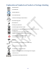
Explanation of Symbols on Product or Package Labeling Model Number Serial Number Read the Manual Consult the Manual Contents of Package are Non‐Sterile Manufacturing Date Manufacturer Warning. Pay attention. Protected against Electric Shock Not waterproof. Applies to the Programmer when it is not in its carrying case. Limited waterproof. Applies to the TNS. Applies to the Programmer in its carrying case. Turns the Programmer ON and OFF. Turns stimulation OFF on the TNS.
Introduction The Clinical Programmer (MN0700) is part of the Spinal Modulation Neurostimulator System. It is intended to be used by the clinical investigator or a Spinal Modulation representative to query and program the Neurostimulator (NS), to retrieve data from the NS and to allow for adjustment of the patient’s therapy. This User Manual gives detailed instructions on how to use the Clinical Programmer safely, how to recharge it and how to use it to set up the patient’s pain management therapy.
Warnings The Warnings listed below pertain to the Clinical Programmer only: • The investigator must be trained by Spinal Modulation personnel before using the Clinical Programmer. • Do not use the Clinical Programmer with a NS device that appears to be faulty or fails to properly communicate. • Improper use of the Clinical Programmer may cause irreversible injury to the patient. All subjects are to be awake and conversant during the procedure to minimize the likelihood of any nerve damage.
Precautions The following precautions should be taken to avoid damage to the Clinical Programmer and to assure proper function: • Do not drop or mishandle the Clinical Programmer. Physical damage to the Clinical Programmer may impair its function. • Do not spill fluids on or wash the Clinical Programmer. Excessive moisture may impair its function. If cleaning is necessary, remove soil with a soft damp cloth. • Do not use abrasive or caustic cleaning products on the Clinical Programmer.
Clinical Programmer System Overview The Clinical Programmer allows you to establish two‐way communication with the patient’s NS device for querying and programming. It is a portable, hand‐held device that can be plugged into a power outlet or be powered by an internal battery. The battery is rechargeable using the Programmer Charger provided and a power outlet.
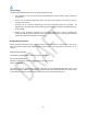
Magnet A magnet is built into the Clinical Programmer. It is located on the back side of the Programmer underneath the indent with the magnet symbol (shown below). The NS system has the capability of detecting the presence of a magnet. The magnet puts the NS device in communication mode, allowing it to connect to the Programmer. An alternate function of the magnet is that by holding the magnet over the device long enough, all stimulation therapy will be switched off.
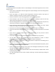
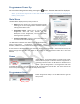
Programmer Power Up Turn the Clinical Programmer ON by pressing the “ “button. The Main Menu will be displayed. NOTE: If the Clinical Programmer screen does not turn on, follow the instructions for charging the battery, and try again. Main Menu The Main Menu displays three primary functions: • Demo: Puts the system into a stand‐alone demo mode allowing you to use all programmer functions without it being connected to a NS.
Change the Date Select the drop down arrow on the right side of the “Set Date” box. A calendar will appear and you can set the month, day and year using your stylus. Change the Time To change the time (24 hour format), first select the hour or minute field that you would like to change. To change the selected field, use the “Up” or “Down” arrows to increase, decrease or toggle the setting. NOTE: Establishing a connection updates the NS device’s clock to the newly set time.
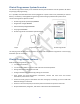
6. Move the Clinical Programmer magnet over the NS device in a circular motion to connect. The indicator status bar on the bottom left of the screen will display “Connected” if the connection attempt is successful. If the Programmer could not communicate with the NS device, an error message will appear and “Disconnected” will be displayed in the status bar.
Programmer Status Bar Located at the bottom of the Clinical Programmer screen, the Programmer Status Bar displays: • Programmer ‐ NS Connection Status: Displays the status of the communication between the Clinical Programmer and the NS device: “Connecting” is displayed when establishing a connection. “Connected” is displayed when there is communication between the Clinical Programmer and the NS device.
Temporary and Permanent Programming Whenever a change is made to a parameter value or other data field while the NS is within telemetry range, this value immediately becomes temporarily active. The corresponding value or data selection appear in a red bold underlined font. Temporary programmed values or text data can be permanently programmed by pressing the program button. The font color changes from red to black.
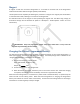
Using the Workspaces Profile Workspace Press the “Profile” tab to access the Profile Workspace.
Clinic Information Tab [Profile >Clinic] Enter or modify the physician and clinic information in the text fields provided: • Physician Name • Clinic Name • Clinic after hours contact phone number • Clinic Phone number • Clinic Email • Clinic Address Stimulator Information Tab [Profile >NS] The NS tab provides a summary of information related to the NS. • Date of Implant: Enter the Stimulator date of use using the drop‐down calendar.
Leads Information Tab [Profile >Leads] Lead 1 through Lead 4 are the default labels used to identify the implanted leads in the “Stim” Workspace. It is recommended that these names be changed into something more meaningful, for example the body region it covers. • Target Name: for each of the implanted leads, enter the body region covered (text field). For each of the leads enter the Lot and Model number: • Lot #: enter the last four digits of the Lot number found on the lead packaging.
Stim Workspace Press the “Stim” tab to access the Stimulation Settings Workspace.
to use this Instant Impedance value for therapy delivery, press the “Transfer Instant Impedance” button (“Æ“). NOTE: The patient may feel the effect of the impedance measurement. Alert the patient to the possible stimulation. NOTE: A transferred impedance value is required before other stimulation parameters can be selected. • Enable: Select “ON” to enable the lead so that it provides stimulation therapy to the patient. Select “OFF” if the lead is not being used.
• Location: Enter the spinal level where stimulation therapy is delivered by this trial lead • Pulse Parameters: To select and change pulse parameters, first press the desired increment level: Fine (>), Medium (>>), Coarse (>>>). Amplitudes below 2.0 mA (>: 25 µA, >>: 50 µA, >>>: 200 µA) Amplitudes above 2.
Impedance Tabs [Stim >Impedance] The impedance button (Ω) initiates impedance measurements between adjacent electrode couples in all of the configured leads and displays on the Imp screen. Map Workspace Press the “Map” tab to access the Map Workspace. The Map Workspace allows you to define which lead connects to each of the NS ports. It therefore provides the ability to automatically move saved settings from one Port to another.
Lead Tabs [Group >Group Name] Each Group can be configured by selecting the desired tab. • Name: The Group can be renamed here (free‐form text entry) • For Patient Use: The Group will be displayed on the Patient Programmer only if this box is checked. Note that the currently active Group must be checked/enabled.
GUIDANCE AND MANUFACTURER’S DECLARATION Electromagnetic Emissions The Spinal Modulation Neurostimulator System is intended for use in the electromagnetic environment specified below. The customer or the user of the Spinal Modulation Neurostimulator System should assure that it is used in such an environment.
Guidance and manufacturer’s declaration Electromagnetic Immunity The Spinal Modulation Neurostimulator System is intended for use in the electromagnetic environment specified below. The customer or the user of the Spinal Modulation Neurostimulator System should assure that it is used in such an environment.
Guidance and manufacturer’s declaration Electromagnetic Immunity The Spinal Modulation Neurostimulation System is intended for use in the electromagnetic environment specified below.
Recommended separation distances between portable and mobile RF communications equipment and the Spinal Modulation Neurostimulation System The Spinal Modulation Neurostimulation System is intended for use in an electromagnetic environment in which radiated RF disturbances are controlled.
Appendix I: Programmable parameters and values Parameter Programmable Values Default Pulse Amplitude 0 – 6000 µA 0 µA 0‐2000 µA (25 µA increments) 2000‐6000 µA (50 µA increments) Maximum Pulse Amplitude Same as Pulse Amplitude 0 µA Pulse Width 40 – 720 µs (10 µs increments) 40 µs Pulse Frequency 4 – 100 Hz (2 Hz increments) 60 Hz Data Field Selectable Values Diagnosis Abdominal Pain; Axial Low Back Pain; Axial Neck Pain; CRPS Type 1; CRPS Type 2; Diabetic Peripheral Neuropathy; FBSS; FNSS;
Appendix II: INS Battery Life The following four tables estimate INS battery life under the given load impedance conditions. Tables 1 through 4 list estimated longevity based on 1‐lead stimulation, active 24 hours a day.
Table 1: Load Impedance = 600 ohms All longevity values are in months Pulsewidth Amplitude Frequency 40uS 100uS 200uS 300uS 400uS 500uS 600uS 700uS 720uS 0.1mA 4Hz 83.9 83.8 83.6 83.4 83.2 83.0 82.8 82.7 82.6 20Hz 81.5 80.9 80.1 79.2 78.3 77.5 76.7 75.9 75.8 40Hz 78.6 77.6 76.0 74.5 73.0 71.6 70.2 68.9 68.6 60Hz 76.0 74.6 72.4 70.3 68.3 66.5 64.7 63.1 62.7 80Hz 73.5 71.8 69.1 66.6 64.2 62.1 60.0 58.1 57.8 100Hz 71.2 69.2 66.1 63.2 60.6 58.2 56.0 53.9 53.5 0.2mA 4Hz 83.8 83.6 83.2 82.8 82.5 82.1 81.7 81.
Table 1: Load Impedance = 600 ohms (Continued) All longevity values are in months 1.0mA 1.5mA 2.0mA 4.0mA 6.0mA 4Hz 20Hz 40Hz 60Hz 80Hz 100Hz 4Hz 20Hz 40Hz 60Hz 80Hz 100Hz 4Hz 20Hz 40Hz 60Hz 80Hz 100Hz 4Hz 20Hz 40Hz 60Hz 80Hz 100Hz 4Hz 20Hz 40Hz 60Hz 80Hz 100Hz Pulsewidth 40uS 100uS 200uS 300uS 400uS 500uS 600uS 700uS 720uS 83.2 82.1 80.3 78.6 76.9 75.4 73.8 72.4 72.1 78.3 73.6 66.9 61.3 56.6 52.5 49.0 46.0 45.4 73.0 65.2 55.4 48.1 42.5 38.1 34.5 31.6 31.0 68.3 58.5 47.2 39.6 34.1 29.9 26.6 24.0 23.
Table 2: Load Impedance = 1 Kohm All longevity values are in months Pulsewidth Amplitude Frequency 40uS 100uS 200uS 300uS 400uS 500uS 600uS 700uS 720uS 0.1mA 4Hz 83.9 83.8 83.6 83.4 83.2 83.0 82.8 82.7 82.6 20Hz 81.5 80.9 80.1 79.2 78.3 77.5 76.7 75.9 75.8 40Hz 78.6 77.6 76.0 74.5 73.0 71.6 70.2 68.9 68.6 60Hz 76.0 74.6 72.4 70.3 68.3 66.5 64.7 63.1 62.7 80Hz 73.5 71.8 69.1 66.6 64.2 62.1 60.0 58.1 57.8 100Hz 71.2 69.2 66.1 63.2 60.6 58.2 56.0 53.9 53.5 0.2mA 4Hz 83.8 83.6 83.2 82.8 82.5 82.1 81.7 81.4 81.
Table 2: Load Impedance = 1 Kohm (Continued) All longevity values are in months 1.0mA 1.5mA 2.0mA 4.0mA 6.0mA 4Hz 20Hz 40Hz 60Hz 80Hz 100Hz 4Hz 20Hz 40Hz 60Hz 80Hz 100Hz 4Hz 20Hz 40Hz 60Hz 80Hz 100Hz 4Hz 20Hz 40Hz 60Hz 80Hz 100Hz 4Hz 20Hz 40Hz 60Hz 80Hz 100Hz Pulsewidth 40uS 100uS 200uS 300uS 400uS 500uS 600uS 700uS 720uS 83.2 82.1 80.3 78.6 76.9 75.4 73.8 72.4 72.1 78.3 73.6 66.9 61.3 56.6 52.5 49.0 46.0 45.4 73.0 65.2 55.4 48.1 42.5 38.1 34.5 31.6 31.0 68.3 58.5 47.2 39.6 34.1 29.9 26.6 24.0 23.
Table 3: Load Impedance = 1.5 Kohm All longevity values are in months Pulsewidth Amplitude Frequency 40uS 100uS 200uS 300uS 400uS 500uS 600uS 700uS 720uS 0.1mA 4Hz 83.9 83.8 83.6 83.4 83.2 83.0 82.8 82.7 82.6 20Hz 81.5 80.9 80.1 79.2 78.3 77.5 76.7 75.9 75.8 40Hz 78.6 77.6 76.0 74.5 73.0 71.6 70.2 68.9 68.6 60Hz 76.0 74.6 72.4 70.3 68.3 66.5 64.7 63.1 62.7 80Hz 73.5 71.8 69.1 66.6 64.2 62.1 60.0 58.1 57.8 100Hz 71.2 69.2 66.1 63.2 60.6 58.2 56.0 53.9 53.5 0.2mA 4Hz 83.8 83.6 83.2 82.8 82.5 82.1 81.7 81.
Table 3: Load Impedance = 1.5 Kohm (Continued) All longevity values are in months 1.0mA 1.5mA 2.0mA 4.0mA 6.0mA 4Hz 20Hz 40Hz 60Hz 80Hz 100Hz 4Hz 20Hz 40Hz 60Hz 80Hz 100Hz 4Hz 20Hz 40Hz 60Hz 80Hz 100Hz 4Hz 20Hz 40Hz 60Hz 80Hz 100Hz 4Hz 20Hz 40Hz 60Hz 80Hz 100Hz Pulsewidth 40uS 100uS 200uS 300uS 400uS 500uS 600uS 700uS 720uS 83.2 82.1 80.3 78.6 76.9 75.4 73.8 72.4 72.1 78.3 73.6 66.9 61.3 56.6 52.5 49.0 46.0 45.4 73.0 65.2 55.4 48.1 42.5 38.1 34.5 31.6 31.0 68.3 58.5 47.2 39.6 34.1 29.9 26.6 24.0 23.
Table 4: Load Impedance = 2 Kohm All longevity values are in months Pulsewidth Amplitude Frequency 40uS 100uS 200uS 300uS 400uS 500uS 600uS 700uS 720uS 0.1mA 4Hz 83.9 83.8 83.6 83.4 83.2 83.0 82.8 82.7 82.6 20Hz 81.5 80.9 80.1 79.2 78.3 77.5 76.7 75.9 75.8 40Hz 78.6 77.6 76.0 74.5 73.0 71.6 70.2 68.9 68.6 60Hz 76.0 74.6 72.4 70.3 68.3 66.5 64.7 63.1 62.7 80Hz 73.5 71.8 69.1 66.6 64.2 62.1 60.0 58.1 57.8 100Hz 71.2 69.2 66.1 63.2 60.6 58.2 56.0 53.9 53.5 0.2mA 4Hz 83.8 83.6 83.2 82.8 82.5 82.1 81.7 81.4 81.
Table 4: Load Impedance = 2 Kohm (Continued) All longevity values are in months 1.0mA 1.5mA 2.0mA 4.0mA 6.0mA 4Hz 20Hz 40Hz 60Hz 80Hz 100Hz 4Hz 20Hz 40Hz 60Hz 80Hz 100Hz 4Hz 20Hz 40Hz 60Hz 80Hz 100Hz 4Hz 20Hz 40Hz 60Hz 80Hz 100Hz 4Hz 20Hz 40Hz 60Hz 80Hz 100Hz Pulsewidth 40uS 100uS 200uS 300uS 400uS 500uS 600uS 700uS 720uS 58.9 58.2 57.2 56.1 55.1 54.2 53.3 52.4 52.2 55.0 52.2 48.2 44.8 41.8 39.2 36.9 34.8 34.4 50.7 46.3 40.3 35.7 32.1 29.1 26.6 24.5 24.2 47.1 41.5 34.6 29.7 26.0 23.1 20.8 18.9 18.
Appendix III: Troubleshooting Pop‐up Messages All stimulation has been turned OFF. Cancelled Connect Request Changes since last programming were lost due to loss of connection with the stimulator. Please reconnect to stimulator. Connected to stimulator. Communication is poor. Connecting to stimulator... Connection Established. Condition Buttons Resolution All stimulation turned off due to data “OK” Contact your Spinal corruption or Device being in Modulation Hibernate mode. Representative.
Programmer storage space is low. Please contact your Spinal Modulation representative for maintenance. Stimulation for one or more leads has been turned OFF. PDA storage is nearing full capacity (log files are stored on the PDA with each significant operation such as programming). Message is displayed and file logging should continue. Normal operation continues after user acknowledgement. One or more leads turned off due to Low Impedance.