Spicer Drive Axles ® Application Guidelines AXAG-0200 June 2009
Table of Contents Important Information about These Guidelines .......................................................................................................5 City Delivery Definitions, General Requirements and Recommendations.....................................................................................6 Single, Tandem Axles & Additional Important Information.................................................................................
Table of Contents (cont’d) 13,500 lb. Housing Structural Ratings .......................................................................................................................47 15,500 lb. Housing Structural Ratings .......................................................................................................................48 17,000 lb. Housing Structural Ratings ......................................................................................................................
Table of Contents (cont’d) Spindle Nut Systems ................................................................................................................................................... 79 Axle Shaft Flange to Hub ........................................................................................................................................... 80 Power Divider Operation ..........................................................................................................................
Important Information about These Guidelines Purpose The purpose of these Drive Application Guidelines is to provide original equipment manufacturer (OEM) builders of medium and heavy duty trucks with information about which Spicer® drive products are approved by Dana Holding Corporation's Commercial Vehicle Products (Dana CVP) for use in common vocational applications in the USA and Canada.
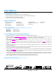
City Delivery Vocational Description n n n n Pickup and delivery service within cities and/or suburban areas 100% of operation on road surfaces of concrete, asphalt and maintained gravel Three (3) miles between starts/stops (typical) 100% load going / up to 40% load return (typical) Typical Vehicle Types Auto Transport Truck Beverage Truck Flatbed Truck Livestock Hauler Moving Van Municipal Truck Newspaper Delivery Pickup and Delivery Refrigerated Truck Roll Back Auto Transporter Stake Truck Tanker Tru
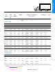
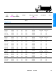
City Delivery Axle Model Max. Max. GAWR SLR (in) (lb) Engine HP Max. Gross Weight (lb) (GVW / GCW) Gear Ratios Torque Operation Operation Operation Fastest (lb-ft) 1 2 3 Notes Slowest Single Axles S14-110 13,500 16.5 325 560 S16-130 15,500 18.1 325 605 17060S 17,000 19.7 300 860 19060S 19,000 20.1 300 860 19055T 19,000 20.1 300 860 21060S 21,000 21.1 300 860 21065T 21,000 21.1 300 860 S21-170 21,000 21.1 400 1450 S21-170E 21,000 21.
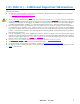
City Delivery - Additional Important Information Important Notes 1. 2. 3. 4. 5. 6. 7. 8. The following optional components are approved by this Guideline. All options may not be available on every axle model. a. Driver Controlled Wheel Differential Lock b. Oil Pump c. Low Maintenance Wheel Ends (LMS) The use of NoSPIN differentials in any drive axle will result in the exclusion of axle shafts from warranty consideration.
Construction/Agriculture Vocational Description n Movement of material to, from, or around a job site n 90% of loaded operation on prepared road surfaces of concrete, asphalt, gravel, crushed rock or hard packed dirt and up to 10% of loaded operation into sandy or muddy work areas. n Liftable tag and pusher axles are often used to increase legal load capacity on highway. n Vehicles typically operate a high percentage of time off-highway making a high number of stops and starts.
Max. Max. GAWR (lb) SLR (in) Engine Max. Gross Weight (lb) (GVW / GCW) Gear Ratios HP Torque (lb-ft) Operation 1 Fastest Slowest 23,000 25,000 29,000 31,000 33,000 33,000 33,000 50,000 50,000 34,000 34,000 34,000 50,000 50,000 50,000 60,000 60,000 60,000 50,000 50,000 50,000 60,000 60,000 60,000 60,000 60,000 60,000 60,000 3.73 5.38 3.73 5.38 3.55 5.57 3.55 5.57 3.55 5.57 3.90/5.32 5.29/7.21 5.32 7.21 3.07 5.57 3.07 5.57 3.55 5.57 3.90/5.32 5.29/7.21 5.32 7.21 3.70/5.04 5.
Max. Max. GAWR (lb) SLR (in) Engine Max. Gross Weight (lb) (GVW / GCW) Gear Ratios HP Torque (lb-ft) Operation 1 Fastest Slowest 66,000 70,000 100,000 72,000 100,000 100,000 100,000 110,000 100,000 110,000 110,000 110,000 110,000 110,000 3.55 5.57 3.55 4.88 3.42 5.38 3.55 5.29 3.70/5.04 4.88/6.64 3.42 5.38 3.42 5.38 4.75 7.75 3.42 4.56 3.42 5.57 4.75 7.75 3.42 4.56 4.75 7.75 4.75 7.75 Notes Tandem Axles DS405-(P) 40,000 21.1 375 1450 DSH40-(P) 40,000 21.
Construction/Agriculture - Additional Important Information Important Notes 1. 2. 3. 4. 5. 6. 7. 8. 9. 10. 11. 12. 13. The following optional components are approved by this Guideline. All options may not be available on every axle model. a. Driver-Controlled Differential Lock b. Oil Pump c. Low Maintenance Wheel Ends (LMS) The use of NoSpin differentials in any drive axles will result in the exclusion of axle shafts from warranty consideration.
Fire Service Vocational Description n Vehicles used to transport people and equipment for the purpose of extinguishing fires or ambulance service n 90% of operation on prepared road surfaces of concrete, asphalt, gravel, crushed rock, or hard packed dirt and up to 10% of n n n n n loaded operation into sandy or muddy areas.
Axle Model Max. GAWR (lb) Max. SLR (in) Engine Max. Gross Weight (lb) (GVW) Gear Ratios HP Torque (lb-ft) Operation 1 Fastest Slowest 16.5 18.1 19.7 20.1 21.1 21.1 21.1 21.1 22.0 22.0 22.0 22.0 22.0 22.0 22.0 22.0 22.7 22.7 22.7 22.
Fire Service - Additional Important Information Important Notes 1. 2. 3. 4. 5. 6. The following optional components are approved by this Guideline. All options may not be available on every axle model. a. Driver-Controlled Differential Lock b. Oil Pump c. Low Maintenance Wheel Ends (LMS) The use of NoSPIN differentials in any drive axles will result in the exclusion of axle shafts from warranty consideration.
Heavy Haul Vocational Description n n n n n Movement of heavy equipment or materials at legal maximums or special permit loadings Exclusive operation on prepared road surfaces of concrete, asphalt and maintained gravel High horsepower engines and auxiliary transmissions are typically used Loaded going and empty return Infrequent stops Typical Vehicle Types Equipment Hauling Flatbed Lowboy Steel Hauling Service Definitions (Vocational descriptions applies to all operations.
Axle Model Max. Max. GAWR (lb) SLR (in) Engine Max Gross Weight (lb) (GCW) HP Torque (lb-ft) Operation 1 Operation 2 22.0 22.0 22.0 22.0 22.0 22.0 22.7 22.7 22.7 625 625 650 625 650 650 650 650 650 2050 2050 2250 2050 2250 2250 2250 2250 2250 190,000 200,000 240,000 200,000 240,000 240,000 240,000 240,000 240,000 175,000 185,000 225,000 185,000 225,000 225,000 225,000 225,000 225,000 19.7 20.1 20.7 20.7 20.
Heavy Haul - Additional Important Information Important Notes The following optional components are approved by this Guideline. All options may not be available on every axle model. a. Driver-Controlled Differential Lock b. Oil Pump c. Low Maintenance Wheel Ends (LMS) 2. The use of NoSPIN differentials in any drive axles will result in the exclusion of axle shafts from warranty consideration.
Intercity Coach Vocational Description n n n n n Transportation of people and, on occasion, light freight between cities or suburban areas Exclusive operation on well maintained paved surfaces High mileage operation Typical vehicle routes exceed 30 miles between start and stop.
Axle Model Max. GAWR (lb) Max. SLR (in) Engine Max. Gross Weight (lb) (GVW) Gear Ratios HP Torque (lb-ft) Operation 1 Fastest Slowest 350 375 475 375 475 1050 1450 1650 1450 1650 45,000 55,000 55,000 55,000 55,000 3.36 3.42 3.42 3.42 3.42 4.78 4.78 4.78 4.78 4.78 Single Axles 22060S S23-170 S23-190 S25-170 S26-190 22,000 23,000 23,000 25,000 26,000 20.7 21.1 21.1 21.1 21.
Intercity Coach - Additional Important Information Important Notes 1. 2. 3. 4. 5. 6. 7. The following optional components are approved by this Guideline. All options may not be available on every axle model. a. Driver-Controlled Differential Lock b. Low Maintenance Wheel Ends (LMS) The use of NoSPIN differentials in any drive axles will result in the exclusion of axle shafts from warranty consideration.
Linehaul Vocational Description n n n n n Long distance transport of various types of freight in high mileage operation (min 60,000 miles/year) Exclusive operation on road surfaces of good to excellent concrete or asphalt Vehicle routes are typically on limited access highways and exceed 30 miles between starts and stops Maximum infrequent grades of up to 8% Majority of vehicles are 4 x 2, 6 x 2 (fixed tag or pusher) and 6 x 4 tractor/trailer combinations and some straight trucks Typical Vehicle Types Aut
Linehaul Axle Model Max. Max. GAWR (lb) SLR (in) Engine HP Max Gross Weight (lb) (GVW / GCW) Torque Operation (lb-ft) 1 Gear Ratios Notes Operation 2 Fastest Slowest 60,000 100,000 60,000 100,000 140,000 50,000 90,000 50,000 90,000 110,000 3.08 5.57 3.07 5.57 3.08 5.57 3.07 5.57 3.07 5.57 90,000 143,000 143,000 143,000 143,000 143,000 185,000 185,000 185,000 90,000 110,000 110,000 110,000 110,000 110,000 160,000 160,000 160,000 3.08 4.11 3.08 4.11 1 3.08 4.11 1 3.36 4.
Linehaul - Additional Important Information Important Notes 1. 2. 3. 4. 5. 6. 7. 8. 9. The following optional components are approved by this Guideline. All options may not be available on every axle model. a. Driver-Controlled Differential Lock b. Oil Pump c. Low Maintenance Wheel Ends (LMS) The use of NoSPIN differentials in any drive axles will result in the exclusion of axle shafts from warranty consideration.
Logging Vocational Description n n n n n Movement of logs, chips and pulp between logging sites mills, or processing plants High horsepower engines and vehicle retarders are typically used in this vocation Vehicle routes are typically 3 to 30 miles between starts and stops Fully loaded going and empty return Majority of vehicles are 6 x 4 tractors or trucks with full trailers unique to this vocation Typical Vehicles Types Chip Hauler Straight Truck with Trailer Log Hauler Tractors with Pole Trailers Ser
Axle Model Max. SLR (in) Engine HP Max. Gross Weight (lb) (GVW / GCW) Torque Operation Operation Operation (lb-ft) 1 2 3 Gear Ratios Fastest Notes Logging Max. GAWR (lb) Slowest Tandem Axles DS405-(P) DSH40-(P) D40-170 DT463-P D46-170H D46-590HP D50-170 D52-190P D52-590P D60-190P D60-590P D70-590P 40,000 40,000 40,000 46,000 46,000 46,000 50,000 52,000 52,000 60,000 60,000 70,000 21.1 21.1 21.1 22.0 22.0 22.0 22.0 22.0 22.0 22.7 22.7 22.
Logging - Additional Important Information Important Notes The following optional components are approved by this Guideline. All options may not be available on every axle model. a. Driver-Controlled Differential Lock b. Oil Pump c. Low Maintenance Wheel Ends (LMS) 2. The use of NoSPIN differentials in any drive axles will result in the exclusion of axle shafts from warranty consideration.
Mining Vocational Description n n n n n n Movement of rock, ore, gravel and minerals around mine sites and between mines and processing plants High horsepower engines are typically used in this vocation Vehicle routes are typically 3 to 30 miles between starts and stops 90% of operation on-road with up to 10% into sandy or muddy job sites Fully loaded going and empty return Tractor/semi-trailer and straight truck/material trailer combinations are considered mining vehicles.
Axle Model Max. Max. GAWR (lb) SLR (in) Engine Max Gross Weight (lb) (GCW) HP Torque (lb-ft) Operation 1 Operation 2 21.1 475 1650 80,000 21.1 21.1 21.1 22.0 22.0 22.0 22.0 22.0 22.0 22.7 22.7 22.7 475 550 625 600 625 625 625 625 625 625 625 625 1650 1850 2050 1850 2050 2050 2050 2050 2050 2050 2050 2050 80,000 80,000 165,000 165,000 165,000 180,000 165,000 180,000 180,000 180,000 180,000 180,000 140,000 130,000 140,000 160,000 140,000 160,000 160,000 160,000 160,000 160,000 19.7 20.1 20.
Mining - Additional Important Information Important Notes 1. 2. 3. 4. 5. 6. 7. 8. 9. 10. 11. 12. 13. 14. The following optional components are approved by this Guideline. All options may not be available on every axle model. a. Driver-Controlled Differential Lock b. Oil Pump c. Low Maintenance Wheel Ends (LMS) The use of NoSPIN differentials in any drive axles will result in the exclusion of axle shafts from warranty consideration.
Motorhome Vocational Description n n n n n n n Vehicles generally used for non-commercial transportation and as traveling domiciles for families Loaded full time May pull small passenger car, boat, or pick-up truck Typically vehicle routes exceed 30 miles between starts and stops Annual mileage generally less than 30,000 Typical operation is on paved roads and short distances within campgrounds and parks Equipped with Automatic transmissions Typical Vehicle Types Recreational Vehicles Integral Coach Veh
Axle Model Max. Max. GAWR (lb) SLR (in) Engine Max. Gross Weight (lb) (GVW / GCW) Gear Ratios HP Torque (lb-ft) Operation 1 Fastest Slowest 300 300 300 300 330 400 330 400 605 660 860 860 1050 1550 1050 1550 27,500 30,000 40,000 42,000 44,000 50,000 45,000 50,000 4.10 4.10 3.55 3.55 3.55 3.58 3.55 3.58 5.38 5.38 5.57 5.57 5.57 5.57 5.57 5.57 Single Axles S14-110 S16-130 17060S 19060S 21060S S21-170 22060S S23-170 13,500 15,500 17,000 19,000 21,000 21,000 22,000 23,000 16.5 18.1 19.7 19.
Motorhome - Additional Important Information Important Notes 1. 2. 3. 4. 5. 6. 7. The following optional components are approved by this Guideline. All options may not be available on every axle model. a. Low Maintenance Wheel Ends (LMS) The use of NoSPIN differentials in any drive axles will result in the exclusion of axle shafts from warranty consideration. Certain other carrier components may also be excluded from warranty consideration if their failure is deemed to be the result of NoSPIN use.
Oil Field Vocational Description n n n n n Movement of production related products, supplies and tools between job sites Movement of processing equipment and laboratories on job sites Low mileage operation on road surfaces made of concrete, asphalt, maintained gravel, crushed rock or hard packed dirt High horsepower engines common Vehicles are typically 6x4 or 6x6 straight trucks or tractors with permanently mounted equipment for well servicing or exploration Typical Vehicle Types Cementing Vehicle Demoli
Axle Model Max. GAWR (lb) Max. SLR (in) Engine Max Gross Weight (lb) (GVW / GCW) HP Torque (lb-ft) Operation 1 Operation 2 21.1 21.1 21.1 21.1 22.0 22.0 22.0 22.0 22.0 22.0 22.0 22.7 22.7 22.
Oil Field - Additional Important Information Important Notes 1. 2. 3. 4. 5. 6. The following optional components are approved by this Guideline. All options may not be available on every axle model. a. Driver-Controlled Differential Lock b. Oil Pump c. Low Maintenance Wheel Ends (LMS) The use of NoSPIN differentials in any drive axles will result in the exclusion of axle shafts from warranty consideration.
Refuse Vocational Description n n n n n 4x2 and 6x4 straight trucks, generally with automatic transmissions, used for residential refuse/recycle pickup. Typically a high number of stops and starts per mile 6x4 straight trucks operating in commercial/industrial pickup with approximately 1 to 3 miles between stops. 6x4 tractor/semi-trailers or 6x4 straight trucks with roll-off containers used for transfer/relocation of material. Stops are typically more than 10 miles apart.
Refuse Axle Model Max. Max. GAWR SLR (in) (lb) Engine Max Gross Weight (lb) HP Torque (lb-ft) Operation 1 Operation 2 (GVW) (GVW/GCW) 21.1 21.1 21.1 21.1 21.1 21.1 21.1 22.0 22.0 22.0 22.0 22.0 22.0 22.0 22.0 22.0 22.0 22.0 22.0 22.7 22.7 22.7 22.
Refuse Axle Model Max. GAWR (lb) Max. SLR (in) Engine HP Torque (lb-ft) 600 625 625 625 625 625 625 625 625 1850 2050 2050 2050 2050 2050 2050 2050 2050 Max Gross Weight (lb) Operation 1 Operation 2 (GVW) (GVW/GCW) Gear Ratios Fastest Slowest 3.70/5.04 3.42 3.42 4.75 3.42 3.42 4.75 3.42 4.75 4.88/6.64 5.57 5.57 6.65 5.57 5.25 6.65 5.25 6.
Refuse - Additional Important Information Important Notes The following optional components are approved by this Guideline. All options may not be available on every axle model. a. Driver-Controlled Differential Lock b. Oil Pump c. Low Maintenance Wheel Ends (LMS) 2. The use of NoSPIN differentials in any drive axles will result in the exclusion of axle shafts from warranty consideration.
Rescue Vocational Description n Specialized all wheel drive vehicles designed for rapid acceleration to airport crash sites n Operation on road surfaces made of concrete, asphalt, maintained gravel, crushed rock, hard packed dirt, or other similar surfaces for 90% of the total miles and sandy or muddy crash sites for the remaining 10% n Extremely low mileage operation n High horsepower engines and automatic transmissions are typical n Vehicle retarders are common (engine, exhaust, transmission, electro-mag
Axle Model Max. Max. GAWR (lb) SLR (in) Engine Max. Gross Weight (lb) (GVW) Gear Ratios Torque (lb-ft) Operation 1 Fastest Slowest 24.5 24.5 24.5 24.5 24.5 24.5 24.5 24.5 24.5 24.5 24.5 24.5 24.5 450 450 525 525 525 450 450 525 525 525 525 525 525 1450 1450 1650 1650 1650 1450 1450 1650 1650 1650 1650 1650 1650 45,000 45,000 47,000 47,000 47,000 50,000 50,000 50,000 50,000 50,000 54,000 54,000 54,000 3.07 3.07 3.07 3.42 4.75 3.07 3.07 3.42 3.42 4.75 3.42 3.42 4.75 5.57 5.57 5.57 5.57 6.65 5.
Rescue - Additional Important Information Important Notes 1. 2. 3. 4. 5. 6. The following optional components are approved by this Guideline. All options may not be available on every axle model. a. Driver-Controlled Differential Lock b. Oil Pump c. Low Maintenance Wheel Ends (LMS) The use of NoSPIN differentials in any drive axles will result in the exclusion of axle shafts from warranty consideration.
School Bus Vocational Description n n n n n Transporting students to and from school and/ or school sponsored events Operation on prepared road surfaces of concrete, asphalt, maintained gravel, crushed rock, or hard packed dirt 2 stops per mile are considered typical Automatic transmissions are typical 100% load going / empty return (typical) Typical Vehicle Types Front Engine Commercial Chassis Rear Engine Integral Coach Front Engine Integral Coach Vehicle Configuration 4 x 2 straight bus Service Defi
Axle Model Max. Max. GAWR (lb) SLR (in) Engine Max. Gross Weight (lb) (GVW) Gear Ratios HP Torque (lb-ft) Operation 1 Fastest Slowest 225 275 300 300 300 310 300 310 520 605 860 860 860 900 860 900 23,000 25,000 29,000 31,000 33,000 38,000 34,000 38,000 4.10 4.10 3.90 3.90 3.90 3.91 3.90 3.91 5.38 5.38 5.57 5.57 5.57 6.14 5.57 6.14 Single Axles 13,500 15,500 17,000 19,000 21,000 21,000 22,000 23,000 16.5 16.5 19.7 20.1 20.1 20.1 20.1 20.
School Bus - Additional Important Information Important Notes 1. 2. 3. 4. 5. 6. 7. The following optional components are approved by this Guideline. All options may not be available on every axle model. a. Driver-Controlled Differential Lock b. Low Maintenance Wheel Ends (LMS) The use of NoSPIN differentials in any drive axles will result in the exclusion of axle shafts from warranty consideration.
13,500 lb. Housing Structural Ratings Housing Dimensions (Standard Track Width) Drive Axle Model (Nominal GAWR (See Note 1) - 13,500 lb.) S14-110 Housing Box Section (H x W x T) 4.25 x 4.25 x .31 Spindle Diameters (Inner/Outer) 4 Spindle Type Varies by Customer Gross Axle Ratings Based on the Use of Outset Single Wheels (lb.) Housing Box Section (in.) 4.25 x 4.25 x .31 74 in. Maximum Track Width Not Approved Notes 2 Gross Axle Rating Based on Site Travel Conditions Only (lb.
15,500 lb. Housing Structural Ratings Housing Dimensions (Standard Track Width) Drive Axle Model (Nominal GAWR (See Note 1) - 15,500 lb.) S16-130 Housing Box Section (H x W x T) 4.25 x 4.25 x .39 Spindle Diameters (Inner/Outer) 2 Spindle Type Varies by Customer Gross Axle Ratings Based on the Use of Outset Single Wheels (lb.) Housing Box Section (in.) 4.25 x 4.25 x .39 74 in. Maximum Track Width Not Approved Notes 3 Gross Axle Rating Based on Site Travel Conditions Only (lb.
17,000 lb. Housing Structural Ratings Housing Dimensions (Standard Track Width) Drive Axle Model (Nominal GAWR (See Note 1) - 17,000 lb.) 17060S Housing Box Section (H x W x T) 5.24 x 4.61 x .38 Spindle Diameters (Inner/Outer) 3.250 / 2.625 Spindle Type L Gross Axle Ratings Based on the Use of Outset Single Wheels (lb.) Housing Box Section (in.) 5.24 x 4.61 x .38 78 in Maximum Track Width Not Approved Notes 2 Gross Axle Rating Based on Site Travel Conditions Only (lb.
19,000 lb. Housing Structural Ratings Housing Dimensions (Standard Track Width) Drive Axle Model (Nominal GAWR (See Note 1) - 19,000 lb.) 19060S 19055T 19055P Housing Box Section (H x W x T) Spindle Diameters (Inner/Outer) Spindle Type 5.24 x 4.61 x .38 3.250 / 2.625 L Gross Axle Ratings Based on the Use of Outset Single Wheels (lb.) Housing Box Section (in.) 5.24 x 4.61 x .38 78 in. Maximum Track Width Not Approved Notes 2 Gross Axle Rating Based on Site Travel Conditions Only (lb.
21,000 lb. Housing Structural Ratings Housing Dimensions (Standard Track Width) Drive Axle Model (Nominal GAWR (See Note 1) - 21,000 lb.) 21060S, S21-170 21065T 21065P Housing Box Section (H x W x T) 5.24 x 4.61 x .43 Spindle Diameters (Inner/Outer) 3.750 / 3.250 5.24 x 4.61 x .38 3.750 / 3.250 Spindle Type R Gross Axle Ratings Based on the Use of Outset Single Wheels (lb.) Housing Box Section (in.) 5.24 x 4.61 x .38 5.24 x 4.61 x .43 78 in.
22,000 lb. Housing Structural Ratings Housing Dimensions (Standard Track Width) Drive Axle Model (Nominal GAWR (See Note 1) - 22,000 lb.) 22060S 22065T 22065P Housing Box Section (H x W x T) 5.24 x 4.61 x .43 Spindle Diameters (Inner/Outer) 3.750 / 3.250 5.24 x 4.61 x .38 3.750 / 3.250 Spindle Type R Gross Axle Ratings Based on the Use of Outset Single Wheels (lb.) (See Note 5) Housing Box Section (in.) 78 in Maximum Track Width 5.24 x 4.61 x .38 5.24 x 4.61 x .
23,000 lb. Housing Structural Ratings Housing Dimensions Drive Axle Model (Nominal GAWR (See Note 1) - 23,000 lb.) 23082T S23-170 S23-190, S23-590 Housing Box Section Spindle Diameters (H x W x T) Spindle Type (Inner/Outer) Standard Track Wide Track 5.24 x 4.61 x .50 5.24 x 4.61 x .56 3.750 / 3.250 R 5.24 x 4.61 x .43 5.24 x 4.61 x .63 3.750 / 3.250 5.24 x 4.61 x .50 5.24 x 4.61 x .63 3.750 / 3.250 Gross Axle Ratings Based on the Use of Wide Track Housings (lb.) Housing Box Section (in.) 5.24 x 4.61 x .
25,000 lb. Housing Structural Ratings Housing Dimensions Drive Axle Model (Nominal GAWR (See Note 1) - 25,000 lb.) S25-170 Housing Box Section Spindle Diameters (H x W x T) (Inner/Outer) Standard Track Wide Track 5.24 x 4.61 x .50 5.24 x 4.61 x .63 3.750 / 3.250 Spindle Type R Gross Axle Ratings Based on the Use of Wide Track Housings (lb.) Housing Box Section (in.) 5.24 x 4.61 x .63 78 in Maximum Track Width 24,000 Notes 2 Gross Axle Ratings Based on the Use of Outset Single Wheels (lb.
26,000 lb. Housing Structural Ratings Housing Dimensions Drive Axle Model (Nominal GAWR (See Note 1) - 26,000 lb.) 26082T S26-190, S26-590 Housing Box Section (H x W x T) Standard Track Wide Track 5.24 x 4.61 x .56 5.24 x 4.61 x .56 5.24 x 4.61 x .63 5.24 x 4.61 x .63 Spindle Diameters (Inner/Outer) Spindle Type 3.750 / 3.250 3.750 / 3.250 R Gross Axle Ratings Based on the Use of Wide Track Housings (lb.) Housing Box Section (in.) 5.24 x 4.61 x .56 5.24 x 4.61 x .
30,000 lb. Housing Structural Ratings Housing Dimensions Drive Axle Model (Nominal GAWR (See Note 1) - 30,000 lb.) S30-190, S30-590 Housing Box Section (H x W x T) Standard Track Wide Track 5.91 x 5.31 x .63 5.91 x 5.31 x .63 Spindle Diameters (Inner/Outer) Spindle Type 4.125 / 3.500 W Gross Axle Ratings Based on the Use of Wide Track Housings (lb.) Housing Box Section (in.) 5.91 x 5.31 x .63 72.5 in. Maximum Track Width 30,000 76 in.
34,000 lb. Housing Structural Ratings Housing Dimensions (Standard Width) Drive Axle Model (Nominal GAWR (See Note 1) - 34,000 lb.) D344 Housing Box Section (H x W x T) 5.24 x 4.61 x .38 Spindle Diameters (Inner/Outer) 3.250 / 2.625 Spindle Type L Gross Axle Ratings Based on the Use of Outset Single Wheels (lb.) Housing Box Section (in.) 5.24 x 4.61 x .38 78 in. Maximum Track Width Not Approved Notes 2 Gross Axle Rating Based on Site Travel Conditions Only (lb.) (See Note 3) Housing Box Section (in.
35,000 lb. Housing Structural Ratings Housing Dimensions Drive Axle Model (Nominal GAWR (See Note 1) - 35,000 lb.) S35-590 Housing Box Section Spindle Diameters (H x W x T) (Inner/Outer) Standard Track Wide Track 6.75 x 5.63 x .88 6.75 x 5.63 x .88 4.125/3.500 Spindle Type W Gross Axle Ratings Based on the Use of Wide Track Housings (lb.) Housing Box Section (in.) 6.75 x 5.63 x .88 75 in.Track Width 35,000 80 in.Track Width 35,000 85 in.
40,000 lb. Housing Structural Ratings Housing Dimensions Drive Axle Model (Nominal GAWR (See Note 1) - 40,000 lb.) D404-(P), DST40-(P) D405-(P), DST41-(P) DSH40-(P) D40-170 Housing Box Section Spindle Diameters (H x W x T) (Inner/Outer) Standard Track Wide Track 5.24 x 4.61 x .38 5.25 x 4.61 x .50 3.750 / 3.250 5.24 x 4.61 x .43 5.25 x 4.61 x .50 3.750 / 3.250 5.24 x 4.61 x .43 5.25 x 4.61 x .50 3.750 / 3.250 5.24 x 4.61 x .43 5.24 x 4.61 x .63 3.750 / 3.
40,000 lb. Housing Structural Ratings (cont’d) Gross Axle Ratings Based on the Use of Outset Single Wheels (lb.) Housing Box Section (in.) 75 in Maximum Track Width 80 in Maximum Track Width 5.24 x 4.61 x .38 5.24 x 4.61 x .43 34,000 36,000 Not Approved 34,000 Notes 3,5 3,5 Gross Axle Ratings Based on Site Travel Conditions Only (lb.) (See Note 4) Housing Box Section (in.) 5.24 x 4.61 x .38 5.24 x 4.61 x .43 73 in.Track (Standard) 54,000 58,000 75 in.Track (Single Wheels) 34,000 48,000 80 in.
44,000 lb. Housing Structural Ratings Housing Dimensions Drive Axle Model (Nominal GAWR (See Note 1) - 44,000 lb.) DSH44-(P) Housing Box Section Spindle Diameters (H x W x T) (Inner/Outer) Standard Track Wide Track 5.24 x 4.61 x .50 5.24 x 4.61 x .50 3.750 / 3.250 Spindle Type R Gross Axle Ratings Based on the Use of Wide Track Housings (lb.) Housing Box Section (in.) 5.24 x 4.61 x .50 75 in.Track (Standard) 43,000 78 in.
46,000 lb. Housing Structural Ratings Housing Dimensions Drive Axle Model (Nominal GAWR (See Note 1) - 46,000 lb.) D463-P D46-170 D46-170H Housing Box Section Spindle Diameters (H x W x T) (Inner/Outer) Standard Track Wide Track 5.24 x 4.61 x .56 5.24 x 4.61 x .56 3.750 / 3.250 5.24 x 4.61 x .50 5.24 x 4.61 x .63 3.750 / 3.250 5.24 x 4.61 x .63 5.24 x 4.61 x .63 3.750 / 3.
46,000 lb. Housing Structural Ratings (cont’d) Gross Axle Ratings Based on the Use of Outset Single Wheels (lb.) Housing Box Section (in.) 5.24 x 4.61 x .50 5.24 x 4.61 x .56 5.24 x 4.61 x .63 78 in. Maximum Track Width 40,000 43,000 46,000 80 in. Maximum Track Width 37,000 41,000 44,000 Notes 3,4 3,4 3,4 Gross Axle Rating Based on Site Travel Conditions Only (lb.) (See Note 5) Housing Box Section (in.) 5.24 x 4.61 x .50 5.24 x 4.61 x .56 5.24 x 4.61 x .63 73 in.
50,000 lb. Housing Structural Ratings Housing Dimensions Drive Axle Model (Nominal GAWR (See Note 1) - 50,000 lb.) D50-170 Housing Box Section (H x W x T) Standard Track Wide Track 5.24 x 4.61 x .63 5.24 x 4.61 x .63 Spindle Diameters Spindle Type (Inner/Outer) 3.750 / 3.250 R Gross Axle Ratings Based on the Use of Wide Track Housings (lb.) Housing Box Section (in.) 5.24 x 4.61 x .63 78 in Maximum Track Width 47,000 Notes 2 Gross Axle Ratings Based on the Use of Outset Single Wheels (lb.
52,000 lb. Housing Structural Ratings Housing Dimensions Drive Axle Model (Nominal GAWR (See Note 1) - 52,000 lb.) D52-190P, D52-590P Housing Box Section (H x W x T) Standard Track Wide Track 5.91 x 5.31 x .63 5.91 x 5.31 x .63 Spindle Diameters (Inner/Outer) Spindle Type 3.750 / 3.250 R Gross Axle Ratings Based on the Use of Wide Track Housings (lb.) Housing Box Section (in.) 5.91 x 5.31 x .63 78 in.Track Width 52,000 80 in.
60,000 lb. Housing Structural Ratings Housing Dimensions (Standard Width) Drive Axle Model (Nominal GAWR (See Note 1) - 60,000 lb.) D60-190P, D60-590P Housing Box Section (H x W x T) Standard Track Wide Track 5.91 x 5.31 x .63 5.91 x 5.31 x .63 Spindle Diameters (Inner/Outer) Spindle Type 4.125 / 3.500 W Gross Axle Ratings Based on the Use of Wide Track Housings (lb.) Housing Box Section (in.) 5.91 x 5.31 x .63 72.5 in. Maximum Track Width 60,000 76 in.
70,000 lb. Housing Structural Ratings Housing Dimensions Drive Axle Model (Nominal GAWR (See Note 1) - 70,000 lb.) D70-590P Housing Box Section (H x W x T) Standard Track Wide Track 6.75 x 5.63 x .88 6.75 x 5.63 x .88 Spindle Diameters (Inner/Outer) Spindle Type 4.125 / 3.500 W Gross Axle Ratings Based on the Use of Wide Track Housings (lb.) Housing Box Section (in.) 6.75 x 5.63 x .88 75 in.Track (Standard) 70,000 80 in.Track Width 70,000 85 in.
Tridem Structural Ratings Housing Dimensions Drive Axle Model T60-174 TD583-P T69-170HP T78-190P, T78-590P Housing Box Section (H x W x T) Standard Track Wide Track 5.24 x 4.61 x .50 5.24 x 4.61 x .50 5.24 x 4.61 x .56 5.24 x 4.61 x. 56 5.24 x 4.61 x .63 5.24 x 4.61 x .63 5.91 x 5.31 x .63 5.91 x 5.31 x .63 Spindle Diameters (Inner/Outer) 3.750 / 3.250 3.750 / 3.250 3.750 / 3.250 3.750 / 3.250 Notes Spindle Type 5 R Gross Axle Ratings Based on the Use of Wide Track Housings (lb.
Dana T78-190P, T78-590P Dana T69-170HP Dana T60-174 Tridem Structural Ratings (cont’d) 78” WT Housing 44,000 46,000 48,000 51,000 53,000 54,000 54,000 54,000 54,000 54,000 53,000 78” Track Single Tire 44,000 46,000 48,000 51,000 53,000 54,000 54,000 54,000 54,000 54,000 53,000 80” Track Single Tire 44,000 46,000 48,000 50,000 50,000 50,000 50,000 50,000 50,000 50,000 50,000 78” WT Hsg 51,000 53,000 55,000 58,000 61,000 64,000 68,000 67,000 69,000 69,000 69,000 69,000 66,000 69,000 78” Track Single Ti
Spicer® Drive Axle Model Identification Note: All options are not available for each model AXAG-0200 June 2009 70
Spicer® Drive Axle Model Identification (Cont’d) Note: All options are not available for each model AXAG-0200 June 2009 71
Spicer® Drive Axle Identification Drive Axle Head Assembly Forward Axle 1 - Country of Origin 2 - Axle Model Identification 3 - Specification number assigned to the axle built by Dana. Identifies all component parts of the axle including special OEM requirements such as yokes or flanges.
Spicer® Drive Axle Identification Parts Identification Ring Gear and Pinion Note: Ring Gear and drive pinion are matched parts and must be replaced in sets.
Nomenclature-General Tandem Axle Assembly 1 - Carrier fasteners 2 - Carrier assembly 3 - Forward axle assembly 4 - Rear axle assembly AXLE HOUSING BOX AXAG-0200 June 2009 74
Nomenclature-General Housing and Output Shaft Assembly 1 - Output shaft nut 2 - Output yoke 3 - Output seal 4 - Output shaft bearing snap ring 5 - Outer bearing cup 6 - Outer bearing cone 7 - Inner bearing cone 8 - Inner bearing cup 9 - Output shaft 10 - Rear cover 11 - Rear cover capsrew 12 - Fill plug 13 - Rear cover nut 14 - Washer 15 - Stud 16 - Spindle nut - outer 17 - Locking ring 18 - Spindle nut - inner 19 - Axle housing 20 - Breather 21 - Breather hose 22 - Carrier capscrew 23 - Nut 24 - Washer
Nomenclature-General Forward Axle Pinion Assembly (Tandem Axle) 1 - Pinion 2 - Pinion bearing cone - inner 3 - Pinion bearing cup - inner 4 - Pinion helical gear 5 - Pinion bearing spacer 6 - Pinion bearing cup - outer 7 - Pinion bearing cone - outer 8 - Pinion nut Rear Axle Pinion Assembly (Single Axle) 1 - Pinion 2 - Pinion bearing cone - inner 3 - Pinion bearing cup - inner 4 - Pinion bearing spacer 5 - Pinion bearing cup - outer 6 - Pinion bearing cone - outer AXAG-0200 7 - Oil seal 8 - Yoke 9 -
Nomenclature-General Wheel Differential 1 - Threaded bearing adjuster (flange half) 2 - Bearing cone (flange half) 3 - Differential case (flange half) 4 - Ring gear 5 - Ring gear bolt 6 - Side gear 7 - Side pinion 8 - Differential spider 9 - Differential case (plain half) AXAG-0200 10 - Differential case (plain half) wheel diff lock 11 - Bearing cone (plain half) 12 - Threaded bearing adjuster (plain half) June 2009 77
Nomenclature-General Power Divider 1 - Output shaft nut 2 - Output yoke 3 - Output seal 4 - Output shaft bearing snap ring 5 - Outer bearing cup 6 - Outer bearing cone 7 - Inner bearing cone 8 - Inner bearing cup 9 - Output shaft 10 - Seal manifold 11 - Clamp 12 - Seal manifold feed tube 13 - Sump screen 14 - Output side gear bearing cup 15 - Output side gear bearing cone 16 - Pin 17 - Output side gear 18 - Pump 19 - Inter-axle differential 20 - Helical side gear 21 - Thrust washer 22 - Lockout sliding cl
Spindle Nut Systems Three-piece Dowel-type Lock Washer System 1 - Inner Nut 2- Dowel Pin 3 - Dowel-type Lock Washer 4 - Outer Nut Three-piece Tang-type Lock Washer System 1 - Inner Nut 2 - Tang-type Lock Washer 3 - Outer Nut Four-piece Tang/Dowel-type Lock Washer System 1 - Inner Nut 2 - Dowel Pin 3 - Dowel-type Lock Washer 4 - Tang-type Lock Washer 5 - Outer Nut Note: Dana does not specify spindle retention systems. This is the responsibility of the OEM.
Axle Shaft Flange to Hub With tapered holes in axle shaft flange With straight holes in axle shaft flange AXAG-0200 June 2009 80
Power Divider Operation Power Flow and Torque Distribution In operation, the power divider accepts torque from the vehicle driveline and distributes it equally to the two axles. This assembly is of the two-gear design consisting of an input shaft, inter-axle differential, output shaft and two constant-mesh helical gears. The inter-axle differential compensates for minor variations in speed between the two axles, the same way the wheel differential works between the two wheels of a single drive axle.
Power Divider Operation Power Flow and Torque Distribution (Cont’d) With Lockout Engaged (Inter-Axle Differential is Not Operating) Note: Varied road surface conditions can result in unequal torque distribution between the two axle assemblies. Lockout should only be engaged when both sides are rotating at the same speed. Operation should be limited to low-traction situations and should be disengaged when normal traction returns.
Wheel Differential Lock The Dana Wheel Differential Lock is a optional feature for Dana Axles. In operation, it positively locks the wheel differential, to provide improved traction under adverse road conditions. The wheel differential lock consists of three major assemblies. The differential lock is driver-controlled through an electric switch or air valve mounted in the cab. The locking mechanism is air-operated to engage a mechanical clutch and lock the wheel differential.
Wheel Differential Lock (Cont’d) Differential Lock Engaged Differential Lock Disengaged Air pressure applied to the shift cylinder moves the piston, push rod, shift fork and the sliding curvic clutch engages the fixed curvic clutch. When air pressure at the shift cylinder is released, a compression spring (mounted on the push rod) moves the push rod, shift fork and sliding clutch as an assembly. The sliding clutch moves out of engagement with the fixed clutch.
Dual Range Tandem Drive Axles Description and Operation Two-Speed, single or tandem, are dual range shiftable axles. They provide low and high range gearing and are designed for heavy-duty service in on-off highway operations. Low range for deep gear reduction and slow speed hauling off highway. High range for cruising speeds on on-highway. The complete tandem axle assembly includes two axle units, each with double gear reduction capability coupled by a 2-gear power divider.
Planetary Double Reduction Axles Description and Operation The planetary double reduction axles share their basic design concepts and many components with the dual range tandem. The principle variation is the permanent engagement of the double reduction feature. A stationary sun gear, fixed in engagement with the lowspeed clutch plate, replaces the sliding clutch gear and provides continuous double reduction operation in the same manner as the dual range axle when in Low Range.
Track, SLR, SMC DUAL TIRES SMC SLR TRACK SINGLE TIRE SMC SLR TRACK TRACK – The distance between the dual tire centerlines or the distance between the tire centerlines on a single tire. SLR (Static Loaded Radius) – The distance from the centerline of axle to the ground, under rated tire capacity, with the tire at rest. SMC (Suspension Mounting Centers) – The distance between suspension mounting points on an axle.
Super Single Tires / Offset Wheels OFFSET WHEELS Track Outset wheel on standard width axle Track Zero offset wheel on standard width axle Track Inset wheel on standard width axle Outset (positive) – The tire centerline is positioned outboard of the wheel mounting face. Inset (negative) – The tire centerline is positioned inboard of the wheel mounting face.
Ratings Charts 40,000 lb Ratings D404-(P), DST40-(P) 21.1 in. Max. Tire SLR; 35.8 in. Min. Spring Mounting Centers 41000 40000 Gawr (lb) 39000 38000 37000 36000 35000 34000 33000 71.5 72 72.5 73 73.5 74 74.5 75 75.5 Track (in) D405-(P), DST41-(P), DSH40-(P), D403-(P) 21.1 in. Max. Tire SLR; 35.8 in. Min.
Ratings Charts (Cont’d) 44,000 lb Ratings Chart DSH44-(P) 21.1 in. Max. Tire SLR; 35.8 in. Min. Spring Mounting Centers 46000 GAWR (lb) 44000 42000 40000 38000 36000 34000 32000 71 72 73 74 75 45,000 lb Ratings Chart 76 77 78 Track (in) 79 80 81 82 83 D451-P 21.1 in. Max. Tire SLR; 35.8 in. Min.
Glossary ABA (Automatic Brake Adjuster) - Also called an Automatic Slack Adjuster (ASA), this is a lever connecting the brake chamber push rod with the foundation brake camshaft. It provides torque to rotate the brake camshaft when the brake treadle is depressed. It also provides a means of automatically adjusting clearance between brake shoes and the drum to compensate for lining wear. Some brake adjusters require manual adjustment.
Glossary AL Factor - A mathematical expression of the brake adjuster and brake chamber combination. "A" equals the effective area, in square inches, of the brake chamber (e.g., Type 30 chamber has effective area of 30 sq.-in.). "L" equals the effective length, in inches, of the slack adjuster. For example, 30 x 6 in. = 180 AL factor Alignment - Method of maintaining proper relationship between all components of the steering system.
Glossary Blue Drum - Brake drum with friction surface turned blue from high temperature. High temperature may result from dragging of brakes caused by weak return springs. Blue drum also may result from lack of brake balance, i.e. excessive brake torque at wheel with Blue drum and lack of brake torque and other wheel ends. Bogie - A combination of two axles usually pivoting about a common trunnion. Brake Adjuster - See "Slack Adjuster".
Glossary Camber, Positive - Top of the wheel tilts outward. Central Tire Inflation System - See "CTIS". Cam Roll-over - Jargon denoting that an S-cam has traveled beyond its designed stopping position during brake application. The wheel end must be removed to repair cam roll-over. It is caused by a combination of excessively worn lining and drum. Channel, ABS - The number of channels in an ABS system refers to the number of valves its Electronic Control Unit (ECU) is capable of independently controlling.
Glossary Companion Flange - Drive shaft side of the joint that connects the drive shaft to the drive axle. Compressible Inserts - Foam inserts installed in the top and bottom of the kingpin under the cap that reduce the pressure / vacuum that is found in the bushing area during typical service. Connectors, ABS - Sealed, corrosion-resistant plugs that link the ABS wiring system to the Electronic Control Unit (ECU), wheel speed sensors and modulator or relay valves using a shielded wiring harness.
Glossary Drain Valve - Used to drain oil and water from air reservoirs. Valve may be manual or automatic in operation. Automatic versions, which may be heated electrically to prevent the valve from freezing open, often are referred to as spitter valves. Draw Key - Fastener in the steer axle that works like a wedge and provides a mechanism to lock the beam to the kingpin while allowing rotation of the knuckle on the kingpin.
Glossary EBS - The abbreviation for Electronic Braking System, or brake-by-wire. A system in which the control signal is sent electronically, rather than pneumatically, although the actual service application is still made by air pressure. ECE 13 - Uniform provisions concerning the approval of vehicles with regard to braking in Europe. ECU, ABS - The abbreviation for Electric Control Unit, is a microprocessor that evaluates how fast a wheel is rotating.
Glossary GAWR (Gross Axle Weight Rating) - The total weight capacity of an axle (single, tandem, or tridem). GCW (Gross Combination Weight) - The weight of a truck and trailer combination and its entire contents. GCWR (Gross Combination Weight Rating) - The total weight capacity of a truck and trailer combination and its entire contents as determined by axle ratings. Gear Ratio, Axle - Ratio of the speed of the propeller shaft to the speed of the rear axle shaft.
Glossary Inversion Valve - Valve used on trucks to release air from the parking brake chambers and apply the rear brakes if the rear air reservoir fails, modulated by the brake pedal. Jackknife - Uncontrollable articulation of a tractor-trailer typically resulting from lock-up or spinning of tractor drive axle(s). The risk of jackknife is greatest on a slippery road with an empty or lightly laden trailer in tow.
Glossary Multiplexing - A means of sending discreet electrical signals to multiple devices along a common pair of wires. Neutral Engagement Valve - A component of pneumatic system that permits the service brake to be applied when the transmission is in neutral and the driver is out of the cab. Typically found on refuse trucks. NoSPIN- Speed sensitive automatic locking differential.
Glossary Pneumatic Timing Balance - Achieved when individual air chambers sequentially receive air within a timeframe that ensures each brake in the system will do its fair share of the work. In a combination vehicle, lack of proper timing is likely to occur because tractor brakes receive air faster than trailer brakes. See "Trailer Push". Pole Trailer - Trailer used to transport utility poles.
Glossary Roll-Off Containers - Detachable open containers generally used for hauling refuse, scrap, and construction debris and are hoisted or winched over the rear of the truck chassis for transport. Rotor - Braking surface for disc brake system. On heavy trucks the rotor is generally cast iron and has vented design. The rotor can be either separate or integral to the hub. Rotors are also referred to a discs.
Glossary Spline - Series of parallel keys cut along the driveshaft that mate with corresponding slots in hub or fitting. Also found on brake camshaft interface to slack adjuster. Stopping Distance - The distance traveled by a vehicle on a road between the initial brake pedal movement and a full stop.
Glossary Thermal Balance - Is achieved when all brakes are operating at the same temperature. If the proper thermal balance is achieved both the tractor and trailer brakes see the same temperature throughout any given braking cycle. On some vehicles, steer axle brake temperatures should be somewhat below drive brakes to avoid aggressiveness and pull. Threaded Drum - Brake drum improperly resurfaced on a lathe, resulting in a friction surface akin to that of a scored drum.
Glossary Trailing Arm Suspension - A suspension with a total of two trailing arms. This suspension forces the axle to travel in an arc which results in a caster change and also torques the axle as the suspension goes into roll. Trailing Axle - See "Tag Axle". Transfer Case - Split power gear box transmitting drive to front and rear axles. Transmission (Main) - Selective gearbox providing various combinations of gear ratios.
Glossary Zerk Grease Fittings - Lubrication fitting used for pressurized grease application. Glossary term sources: Dana Engineering www.100megsfree4.com/dictionary/car-dicm.htm Commercial Carrier Journal with permission to use material from ‘Air Disc Brakes’ granted by C. Magner of Randall Publishing Co.
Revisions 1) Cover Page - Changed date on this and all pages to latest released date (month and year) 2) Table of Contents - Added ‘Agriculture’ to Construction 3) Changed ‘Dana Corporation’ to ‘Dana Holding Corporation’, wherever used. 4) Changed ‘CVS’ to ‘CVP’, wherever used 5) Changed ‘Dana Corporation Commercial Vehicle Systems’ to ‘Dana Holding Corporation Commercial Vehicle Products’ on page 5 6) Changed ‘Spicer Warranty Guide (TCWY-0900)’ to ‘Spicer Warranty Guide (TCWY0900)’, wherever used.
Revisions (cont’d) 13) Heavy Haul (page 16) • Changed ‘See Page 81’ to ‘See Page 80’ • Added bullet point ‘All electrmagnetic retarders, such as Telma, require individual application approval by the Dana CVP application engineering department’ • Added bullet point ‘Dana CVP application approval is required for all vehicles with hybrid power systems’ 14) Heavy Haul (page 17) • Changed the Fastest Gear Ratio for the D46-170H and D50-170 axle models from 3.31 to 3.
Revisions (cont’d) 23) Motorhome (page 31) • Changed ‘See Page 81’ to ‘See Page 80’ • Added bullet point ‘All electrmagnetic retarders, such as Telma, require individual application approval by the Dana CVP application engineering department’ • Added bullet point ‘Dana CVP application approval is required for all vehicles with hybrid power systems’ 24) Motorhome (page 32) • Changed Max.
Revisions (cont’d) 33) 15,500 lb. Housing Structural Ratings (page 48) • Added ‘Spindle Type’ and ‘Varies by Customer’ to the Housing Dimensions (Standard Track Width) chart 34) 17,000 lb. Housing Structural Ratings (page 49) • Added ‘Spindle Type’ and ‘L’ to the Housing Dimensions (Standard Track Width) chart 35) 19,000 lb.
Revisions (cont’d) 40) 26,000 lb. Housing Structural Ratings (page 55) • Added ‘Spindle Type’ and ‘R’ to the Housing Dimensions chart • Added Note 5 • Added ‘(See Note 5)’ to the Gross Axle Ratings Based on Outset Single Wheels (lb.) chart • Changed 72 in. Track (Standard) to 73 in. Track (Standard) in the Gross Axle Ratings Based on Site Travel Conditions Only (lb.) chart 41) 30,000 lb.
Revisions (cont’d) 47) 50,000 lb. Housing Structural Ratings (page 64) • Added ‘Spindle Type’ and ‘R’ to the Housing Dimensions chart • Changed ‘72 in. Track (Standard)’ to ‘73 in. Track (Standard)’ in the Gross Axle Ratings Based on Site Travel Conditions Only (lb.) chart 48) 52,000 lb. Housing Structural Ratings (page 65) • Added ‘Spindle Type’ and ‘R’ to the Housing Dimensions chart • Removed ‘85 in. Track Width’ and ‘45,000’ from the Gross Axle Ratings Based on the Use of Wide Track Housings (lb.
Aftermarket ForDana spec‘ing or service Group assistance, call 1.800.621.8084 or visit our website at www.spicerparts.com PO Box 321 Toledo, Ohio 43697-0321 Warehouse Distributor: Dana Commercial Vehicle1.800.621.8084 Products Group OE Technology Dealers: 1.877.777.5360 3939 Drive Maumee, Ohio, USA 43537 www.spicerparts.com www.dana.com AXAG-0200 Printed in U.S.A. Copyright Dana Limited, 2012. All rights reserved. Dana Limited.