
Users Manual Part 2


39
HDE 11/2018 732.29.128
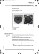
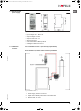
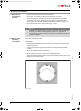
3. Connect the connection leads to the clips (fig. 10/1) of the reader.
Fig. 10: Terminal clamps on the rear
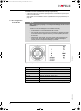
4. Screw cover to rear of WT 210 (fig. 11/1). Lead out the leads to the padded cable
guides at the side (fig. 11/2).
Fig. 11: Rear of WT 210 with lead
NOTE
Risk of damage to the leads!
The connection leads can be damaged in the event of incorrect installation.
• Carefully push the reader and lead into the switch box.
• Ensure that the leads are not trapped.
1
+
-
-
ins-src-732.29.128.book Seite 39 Dienstag, 20. November 2018 10:27 10