
User guide

55
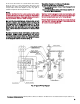
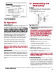
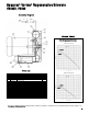
FFiigg.. 44 TTyyppiiccaall NNaammeeppllaattee
IIIIII.. OOppeerraattiioonn
LLiimmiittss ooff OOppeerraattiioonn
Oper
ation at flows less than those indicated by the solid
line on the applicable performance curve will cause
overheating of the unit and is to be avoided.
TThhrroottttlliinngg
ssuuccttiioonn oorr ddiisscchhaarrggee ppiippiinngg ttoo rreedduuccee aaiirr vvoolluummee
iinnccrreeaasseess ddiiffffeerreennttiiaall pprreessssuurree rreessuullttiinngg iinn eelleevvaatteedd
tteemmppeerraattuurree aanndd iinnccrreeaasseedd ppoowweerr ccoonnssuummppttiioonn.. UUssee
ooff pprreessssuurree aanndd// oorr vvaaccuuuumm rreelliieeff vvaallvvee rreeccoommmmeennddeedd..
Maximum pressure and vacuum are indicated on the
nameplate (see Fig. 4). These represent conditions at
which the minimum allowable airflow (CFM) occurs.
Check the operating pressure or vacuum to assure that
the pressure or vacuum remains less than maximum.
For continuous operation at low air volume (on the
dotted portion of the performance curve), provide a
bypass in the piping and operate at a lower pressure
than maximum operating pressure. See Performance
Curves, Section V.
CCaauuttiioonn:: LLooww ffllooww ccoonnddiittiioonnss mmaayy pprroodduuccee hheeaatt lleevveellss
wwhhiicchh mmaayy ccaauussee bbuurrnnss.. DDoo nnoott ttoouucchh tthhee bblloowweerr iinn
ooppeerraattiioonn..
TTeemmppeerraattuurree RRiissee
A NEMA Class F insulation system is used in the motor.
Maximum allowable winding temperature is 265˚F. If a
thermal protector or thermal relay activates because the
temperature rise of the motor is higher than usual, inves-
tigate and correct the problem. Explosion-proof motors
use a NEMA Class B insulation. Typical causes of motor
overheating are given in Section VI, Troubleshooting
Guide.
IIVV.. DDiissaasssseemmbbllyy aanndd
RReeaasssseemmbbllyy
AA.. GGeenneerraall
1. Pre
cautions should be taken when disassembling
or reassembling the blower. See Warranty Terms.
2. Keep all parts clean.
3. Do not overtighten bolts and screws.
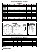
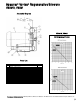
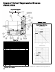
FFiigg.. 55 IImmppeelllleerr PPuulllleerr
BB.. DDiissaasssseemmbbllyy PPrroocceedduurree ((RReeaasssseemmbbllyy iiss ppeerrffoorrmmeedd
iinn rreevveerrssee oorrddeerr))
CCaauuttiioonn:: SShhiimmss aarree uusseedd ttoo aaddjjuusstt tthhee ggaapp bbeettwweeeenn
tthhee iimmppeelllleerr aanndd ccaassiinngg.. WWhheenn ddiissaasssseemmbblliinngg,,
ttaakkee ccaarree ttoo nnoottee tthhee qquuaannttiittyy ooff sshhiimmss aanndd tthheeiirr
tthhiicckknneessss.. TThhee sshhiimm ssttaacckk rreeppllaacceemmeenntt mmuusstt bbee
tthhee ccoorrrreecctt tthhiicckknneessss ttoo aassssuurree pprrooppeerr cclleeaarraannccee
aanndd ttoo aavvooiidd ddeeggrraaddaattiioonn ooff ppeerrffoorrmm
aannccee..
1. Re
move impeller cover; remove screws, pull cover
away from case.
2. Unfasten lock washer; remove nut and washer.
3. Remove impeller from shaft by one of the following
methods:
a. manually pull the impeller outward, OR
b. screw two bolts into tapped holes and pull on
the bolts, OR (if the fit is tight)
c. use a puller assembly (not furnished) as shown in
Fig. 5.
4. Remove motor shaft key.
5. Remove case from motor; if necessary remove
screws holding case to base and motor to case.
6. Remove shims from motor shaft if necessary; do
not discard them. See Note above.
C
C
a
a
u
u
t
t
i
i
o
o
n
n
:
:
M
M
o
o
t
t
o
o
r
r
s
s
a
a
r
r
e
e
h
h
e
e
a
a
v
v
y
y
.
.
L
L
i
i
f
f
t
t
m
m
o
o
t
t
o
o
r
r
o
o
n
n
m
m
o
o
d
d
e
e
l
l
s
s
llaarrggeerr tthhaann VVBB000022 bbyy tthhee eeyyeebboolltt oonn tthhee mmoottoorr wwiitthh
a
a
n
n
a
a
i
i
d
d
f
f
r
r
o
o
m
m
a
a
l
l
i
i
f
f
t
t
i
i
n
n
g
g
d
d
e
e
v
v
i
i
c
c
e
e
.
.
CC.. RReeaasssseemmbbllyy GGuuiiddaannccee
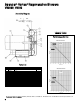
1. T
he gap between the impeller and case is essential for
proper performance of the unit. The shims between
the shaft collar and impeller hub establish the spacing
of this gap. In reassembly, before installing the
impeller cover, check the gap between the impeller
and case to assure that the measurement conforms to
the gap specification on the assembly drawing (on the
following pages) for your unit.
TThhee SSppeenncceerr TTuurrbbiinnee CCoommppaannyy
◆ 600 Day Hill Road, Windsor, CT 06095 ◆ TEL 800-232-4321 ◆ 860-688-8361 ◆ www.spencerturbine.com
YYeeaarr ooff PPrroodduuccttiioonn
THREADED
PLATE
SHIM BLOCK
MOTOR
“C” FACE
IMPELLER
HUB
SHAFT
BOLT