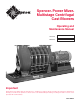
Spencer Power Mizer Multistage Centrifugal Cast Blowers ® ® Operating and Maintenance Manual Serial No. Model No. Important Read and become familiar with this manual prior to installing your Spencer blower. Following the instructions detailed here will help you realize its full potential of efficient service and extended lifespan. Damage resulting from failure to follow correct procedure will void the warranty. Form WW6.
Contents Page I Introduction................................................................... 2 Product Description......................................................... 3 II Limited Warranty........................................................... 3 III Safety Precautions and Operating Guidelines........... 4 IV Handling and Storage................................................... 4 Lifting and Moving........................................................... 4 Storage..............
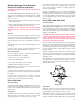
Product Description Spencer Power Mizer blowers are multistage centrifugal units which handle air and other gases, working either as blowers or exhausters. They increase the pressure of the incoming air or gas by guiding it from one stage to the next through diffusers. They are centrifugal because the flow through the blower is turned perpendicular to the axis of rotation. The blower casing has three main sections constructed of cast iron: inlet, return channels and discharge.
III. S afety Precautions and Operating Guidelines • Read and follow all instructions in this manual. If you have any questions, consult your Spencer Representative. • Use appropriately rated lifting equipment for installation, removal, or disassembly of heavy components. • Remove inlet and discharge covers, silica gel bags and crating materials prior to blower installation. • Inspect all openings for tools and foreign matter before connecting accessories or piping.
Use lifting eyes supplied on the blower base, along with a suitable quad leg chain sling or spreader bars with the smallest practical angle between the sling legs to minimize stress. CAUTION: Do not use slings around the blower; they will bend or stress the tie rods. Never lift the blower by its shaft. Do not disturb the oilers or any electrical devices. Storage If a blower is stored for an extended period before use or between uses, protect it from dampness, dirt and vibration.
3. Butterfly Valve To regulate (throttle) blower volume and/or pressure, a butterfly valve may be installed–preferably on the inlet. A valve may also be installed on the discharge as an isolation valve. 4. Filters, Silencers and Filter Silencers Spencer blowers will accept a filter or filter silencer, typically on the inlet, and a silencer, typically on the discharge. Inlet filtration is recommended for pressure applications. 5.
WARNING: REPLACE THE COUPLING GUARD BEFORE RESTARTING THE BLOWER. 8. Bearing Lubrication Motor Bearings. Follow the motor manufacturer’s recommendations. Some motors are equipped with sealed bearings not intended for relubrication; these motors have no grease or drain plugs. Blower Bearings–Grease Lubricated. These bearings are packed at the factory and do not need greasing prior to startup.
Blower Startup With the system connected and the throttling valve closed, turn the blower on. Quickly assess the current draw of the motor. Adjust the system load or throttling valve until the desired flow is reached, being careful not to exceed the full-rated motor capacity. Initially, blowers will temporarily develop more differential pressure and take more power. Check final settings after operating temperature is achieved, typically after one-half hour.
Blower Bearings–Oil Lubricated General Oil Lubrication Information CAUTION: If equipped with oiler, keep the oiler at least 1/3 full at all times. Use Mobil SHC626 synthetic oil or equivalent (see list, page 7). Each blower is shipped with an adequate amount of Mobil SHC626 oil for one oil change. The oil should be changed at least once a year. 1. Drain oil (preferably when hot) by removing the drain plug in the bearing sump. 2.
The fill rate is slow on Series 3000, 4000, 5000, and 6000 machines. Let these machines sit, preferably overnight, until the oil is stabilized. If waiting is not possible, fill the sumps from the top vent–recognizing that this procedure can result in high oil levels as oil drains off internal components. Series 7000, 8000 Oil Height Settings Power Mizer Series 7000 and 8000 blowers have nonadjustable oilers hard-piped directly into the sump.
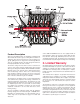
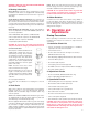
Series 1500 (Grease) Series 2500, 3500 (Grease) Bearing Housing Bearing Housing Grease Slinger Bearing Lockwasher Locknut Gasket Bearing Cap Bearing Cap Bearing Lockwasher Locknut Bearing Housing Series 2500, 3500 (Oil) Grease Slinger Bearing Gasket Lockwasher Locknut Spacer Sump Oil Slinger Gasket Bearing Cap Bearing Housing Series 3000, 4000, 5000, 6000 (Oil) Oiler Bracket Vent Hose Bronze Seal Gasket Bearings, Back to Back Lockwasher Oiler Feed Hose Locknut Bearing Cap Gasket Bearing
NOTE: No shaft support is needed; the shaft will be supported by the labyrinth seals. Bearing Replacement Procedure CAUTION: Maintain extreme cleanliness to avoid bearing contamination and damage. Use new gaskets. 1. Install components in the reverse order of disassembly. 2. Press the bearing onto the shaft until seated against the shoulder. Pusher kits are available from Spencer. NOTE: If present, oil slinger ‘dimples’ should face the bearing. 3. Lubricate according to instructions on pages 8 and 9.
Field-Replaceable Parts When ordering parts provide full information about your Spencer equipment, including the serial number and model number. Field-replaceable parts are restricted to the following: • • • • • • Drive end motor bearing Opposite drive end motor bearing Inlet bearings Discharge bearing Labyrinth seal or carbon ring Bearing cap gaskets Equipment Service Spencer provides prompt, courteous factory and field service for all Power Mizer machines.
IX. Troubleshooting Guide (cont.) PROBLEM Possible Cause Corrective Action MACHINE NOISY Indication: machine malfunction – bearing whining or growling • Bearing hot. Check lubricant, add or drain as necessary. Be sure oiler is functioning properly and screw cap is tightened properly. • Bearing failure. Replace bearing(s). • Bearing retainers worn. Replace bearing(s). • Bearing turning on shaft, retaining nut loose. Tighten nut, check for damage. • Bearing turning in housing, housing worn.
IX. Troubleshooting Guide (cont.) PROBLEM Possible Cause VIBRATING MACHINE Indication: mechanical fault • Material buildup on impellers. Consult Spencer Service Department for cleaning instructions, install inlet filter to prevent further buildup. • Shaft bent. Consult Spencer Service Department. • Bearing failure. Replace bearing(s). • Unbalanced replacement motor installed. Balance motor. • Internal parts hitting. Consult Spencer Service Department. • Impeller failure.
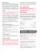
Spencer Corporate Headquarters and Manufacturing Plant, Windsor, CT USA ® Products & Services Industrially rated products offering effective solutions for air and gas handling problems • Multistage centrifugal blowers • Single-stage centrifugal blowers • High-speed turbo blowers • Gas boosters & hermetic gas boosters • Regenerative blowers • Modular central vacuum systems • Mobile or stationary integrated vacuum systems • Dissolved oxygen control systems • Comprehensive selection of tubing, fittings,