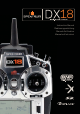
8 18 ® Instruction Manual Bedienungsanleitung Manuel d’utilisation Manuale di Istruzioni ®
EN NOTICE All instructions, warranties and other collateral documents are subject to change at the sole discretion of Horizon Hobby, Inc. For up-to-date product literature, visit horizonhobby.com and click on the support tab for this product.
EN Welcome to a new era of RC precision and freedom. With the DX18 you can fly just about anything you want exactly the way you want to. And you’ll do so with less hassle than ever before. Its wide array of Spektrum™ AirWare™ programming functions is the most powerful ever made available in a handheld transmitter.
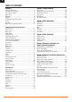
EN TABLE OF CONTENTS Chapter 1 Chapter 2 ACRO (Airplane) Transmitter Batteries ....................................................5 Charging Your Transmitter .............................................5 Transmitter Functions ...................................................6 Main Screen ................................................................8 Navigation ...................................................................8 Binding...............................................................
EN TRANSMITTER BATTERIES Battery and Charging Precautions and Warnings Failure to exercise caution while using this product and comply with the following warnings could result in product malfunction, electrical issues, excessive heat, FIRE, and ultimately injury and property damage.
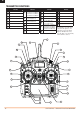
EN TRANSMITTER FUNCTIONS Function 1 Antenna 1 2 RIght Trim 3 Right Knob 4 Switch E 5 6 7 Function Switch H Switch G Switch F Function Function Throttle/Aileron Stick (Mode 1) Elevator/Aileron Stick (Mode 2) Throttle/Rudder Stick (Mode 3) Elevator/Rudder Stick (Mode 4) 15 Clear Button 22 Switch B 16 Back Button 23 Switch A 17 24 Switch D 9 Elevator Trim (Mode 2, 4) Throttle Trim (Mode 1, 3) Speaker Grill 18 Bind/Switch I Aileron Trim (Mode 1,2) Rudder Trim (Mode 3,4) Rudder Tr
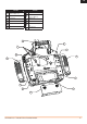
EN Function Function 1 Throttle Spring Tension Adjustment (Mode 2,4) 7 Charge Port 2 Left Lever 8 Throttle Spring Tension Adjustment (Mode 1,3) 3 Left Rear Grip 9 Right Rear Grip 4 Trainer Port 10 Right Lever 5 SD Card 11 Gimbal Stick Tension Adjustment 6 Battery Cover 12 Handle/Antenna 2 12 1 11 2 10 3 9 4 8 7 5 6 SPEKTRUM DX18 • TRANSMITTER INSTRUCTION MANUAL 7
EN Main Screen Function A Model Memory B Model Name C Transmitter Battery Charge Level D Digital Battery Voltage (an alarm sounds and the screen flashes when battery charge gets down to 4.3V when using an NiMH battery or 6.4V for a LiPo battery.
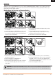
EN BINDING Binding is the process of programming the receiver to recognize the GUID (Globally Unique Identifier) code of a single specific transmitter. The DX18 and AR9020 are pre-bound at the factory. You will need to rebind after the model programming is initially set up to fully program the model’s failsafe positions. Binding Using the Receiver and Receiver Battery 2. 3. 4. Hold button while powereing on 5. 6. 1. Mode 2 shown 1.
EN PROGRAMMING FAILSAFE POSITIONS You establish failsafe positions when you bind your transmitter and receiver. If radio signal connection is lost between the transmitter and receiver, the receiver immediately moves the aircraft control surfaces to the failsafe positions. The Spektrum AR9020 receiver has three failsafes programming options: SmartSafe, Hold Last Command, and Preset.
EN X-PLUS™ X-Plus Channels and Failsafe Failsafe is not supported for servos connected to the X-Plus Module. We recommend that no failsafe should be expected or attempted for a servo connected through the X-Plus Module. However, servos connected to the X-Plus Module will hold last command in the event of a failsafe condition. To Activate X-Plus 1. Open the Frame Rate Menu in System Setup. 2. Scrolll to X-Plus and press the scroll wheel to activate.
EN MODEL TYPE PROGRAMMING GUIDE Menu options show upon model type selection. These menu options vary between Model Types (Airplane Helicopter and Sailplane), but are identical for all models in that type. Subsequent aircraft type (AIrcraft, Swashplate or Sailplane) selections make other menu options appear.
EN COMMON SYSTEM SETUP FUNCTIONS SYSTEM SETUP Model Select Model Select enables you to access any of the 50 internal model memory locations in the Model Select list. 1. Scroll to the desired model memory in the Model Select list. 2. When the desired model memory is highlighted, press the scroll wheel once to select the model. The transmitter returns to the System Setup List. Direct Model Access Press the Clear and Back buttons from the Main Screen or a telemetry screen to access Model Select.
EN F-Mode Setup Use the Flight Mode Setup menu to assign switches to flight modes.
EN Channel Input Configuration The Channel Input Configuration screen enables you to assign a transmitter channel to a different control stick or switch. 1. Select NEXT on the RX Port Assignments screen to access the Channel Input Configuration screen. 2. Scroll to the transmitter channel you wish to re-assign and press the scroll wheel. The box around the current input selection flashes. 3. Scroll left or right to select the desired control stick or switch. 4. Press the scroll wheel to save the selection.
EN Model Copy The Model Copy menu enables you to duplicate model programming from one Model List location to another. Use Model Copy to: • Sort the models in the Model List by brand, model type or power source • Save a default model copy before experimenting with programming values • Expedite programming for a model using a similar programming setup. IMPORTANT: Copying a model program from one model memory to another will erase any programming in the “To” model memory. 2.
EN Enabled When Enabled is set to NO, Data Logging is turned off. Select YES to save Telemetry data to the SD Card. The SD Card must be installed in the transmitter to select YES. CAUTION: If you access the Telemetry menu from the Function List, you may see a Frame Loss appear when you exit the menu. The Frame Loss is not an error, however there is a momentary loss of radio signal when exiting the Telemetry screen. Do NOT access the Telemetry menu during flight.
EN Trainer The DX18 features a programmable trainer function with 4 trainer modes. The transmitter assigns the trainer function to Switch I. The 4 trainer modes include: Slave Inhibit DX18 Trainer Operation In Inhibit, the slave transmitter must have the same programming as the master transmitter (e.g., servo reversing, travel adjust, sub-trim, trims).
EN System Settings The System Settings menu consists of four screens: System Settings, Extra Settings, Serial Number and Calibrate. Select NEXT or PREV to move between screens. User Name The User Name field displays your name in the lower right corner of the main screen. To Program a User Name 1. Scroll to User Name and press the scroll wheel. The User Name screen appears. 2. Scroll to the desired character position and press the scroll wheel.
EN Inactive Alarm An alarm activates if the transmitter sees a period of inactivity for a certain amount of time. The alarm is helpful in reminding you to power off the transmitter and avoiding a situation when the transmitter battery completely discharges.
EN Calibrate The Calibration screen stores the potentiometer endpoints for all proportional controls. It is mandatory to complete the calibration after changing the stick mode selection. Calibrating the Transmitter 1. Carefully move the gimbal sticks in a + shape moving from left to right, then up and down. Press gently on the gimbals at the stops to achieve an accurate calibration. Return both gimbal sticks to the center position. 2.
EN Automatically Installing AirWare Updates To install the most recent AirWare update: 1. Download the update from Community.SpektrumRC.com and save it to the SD Card. 2. Power off the transmitter and install the SD Card in the transmitter. 3. Power on the transmitter and the update automatically installs in the transmitter. Manually Installing AirWare Updates 1. Save the desired AirWare version to the SD Card. 2. Select Update Firmware in the SD Card Menu options. The Select File screen apepars. 3.
EN Absolute (Abs.) Travel Balance The Abs. Travel function limits the amount of travel on a channel. Adjust the Abs. Travel value to prevent a throttle servo or helicopter cyclic servo from binding when a mix is applied. Balance is available on all channels to fine-tune the servo position at up to 7 points. This is a precision curve mix that is normally used to prevent binding when multiple servos are used on a single control surface.
EN V-Tail Differential (Air and Sail Types only) The V-Tail Differential screen enables you to increase or decrease the amount of differential between control surface throws. Positive Differential values decrease the amount of “up” travel without affecting the “down” travel on the opposite control surface. Negative Differential values decrease the amount of “down” travel without affecting the amount of “up” travel on the opposite control surface.
EN Mixing Mixing allows control input for a channel to affect more than one channel at a time. Mixing functions support: • Mixing a channel to another channel. • Mixing a channel to itself. • Assigning offset to a channel • Linking primary to secondary trim. CAUTION: Always do a Control Test of your model after changing mixes.
EN Sequencer The Sequencer menu option provides this-then-that mixing with a time delay. Five different sequences (S1 through S5) are available to control 2 functions each (A and B), in 2 timing directions (forward or reverse). Sequences appear throughout function screens as assignable switches. CAUTION: Always review the action of a sequence on the Monitor or X-Plus Monitor screen BEFORE operating the model to ensure controls act as desired.
EN Range Test The Range Test function reduces the power output. This allows for a range test to confirm the RF link is operating correctly. Perform a range check at the beginning of each flying session to confirm system operation. To Access the Range Test screen With the transmitter on and the main or telemetry screen displayed, press the roller. The Function list displays. Rotate the roller to highlight Range Test then press the roller to access the Range Test function.
EN Monitor The Monitor screen displays the servo positions for each channel graphically and numerically. This is useful to verify programming functions, trim settings, mix directions, etc. The numeric value is directly relative to the travel adjust and mix values (e.g., 100% travel adjust equals 100% value in the Monitor). X-Plus Monitor Use of the X-Plus Monitor requires X-Plus to be active. The X-Plus Monitor screen displays the output position for each X-Plus channel graphically and numerically.
EN CHAPTER 2 ACRO (Airplane) NOTICE: Refer to your airplane manual for recommended control throws. CAUTION: Always do a Control Test of your model with the transmitter after programming to make sure your model responds as desired. Aircraft Type Use the Aircraft Type Screen to select wing and tail types to match your airplane model. Diagrams and setup names show on the transmitter screen to show the available setups. Refer to community.spektrumrc.
EN Flap System The Flap System menu option enables flap programming as well as elevator mixing. You must select a flap-enabled wing type in Aircraft Type or the Flap System menu does not appear. To activate the Flap System: 1. Access the System Setup list and select Aircraft Type. 2. Select a flap-enabled wing type and exit the System Setup list. 3. Access the Function List from the Main Screen and select Flap System. 4.
EN CHAPTER 3 HELI (Helicopter) NOTICE: Refer to your helicopter, gyro and governor manuals for programming recommendations. CAUTION: Always do a Control Test of your model with the transmitter after programming changes to make sure your model responds as desired. Swash Type The Swash Type menu option assigns the swash type for your particular helicopter model. Select the Swash Type before completing any programming in the Function List. The Swash Type will affect menu options in the Function List.
EN Gyro The Gyro menu option enables you to assign a gyro gain value to an independent switch or a Flight Mode. Assign the receiver channel connected to the gyro, then assign the switch for gyro options. You can also assign values to available switch positions (from 1 to 5 rates are available, depending on the switch assigned). Make sure the gyro operates correctly and compensates in the correct direction. Governor The Governor function adjusts the engine RPM.
EN CHAPTER 4 SAIL (Sailplane) NOTICE: Refer to your sailplane manual for recommended control throws. CAUTION: Always do a Control Test of your model with the transmitter after programming to make sure your model responds as desired. Sailplane Type Use the Sailplane Type Screen to select wing and tail types to match your sailplane model. Diagrams and setup names show on the transmitter screen to show the available setups. Refer to community.spektrumrc.
EN SAIL Mixing Elevator to Flap For each of these mixes, you can program each flight mode with different mix values or at 0% if no mix is desired for that specific flight mode. Programming values include independent control of the direction and amount a slave surface moves in relationship to the master surface. Elevator to Flap mix creates additional lift, allowing a tighter turn. The entire trailing edge of the wing (aileron and flap) operate as flaps (camber increase) when you apply elevator.
EN NOTICE: The DSMX DX18 is compatible with all current Spektrum DSM2 and DSMX aircraft receivers, but NOT compatible with the original DSM AR6000 receiver. Power System Requirements Set up and operate a model so power to the receiver is NEVER interrupted while flying. This is especially critical on giant-scale models that use several high-torque or high-current servos. Power systems unable to provide minimum receiver voltage in flight are the number-one cause of in-flight failures.
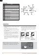
EN Function 1 Throttle friction strip tension screws 2 Gimbal spring covers 3 Friction straps access screws (Throttle Ratchet Strip installation) 1 2 3 Adjust Throttle Friction Straps • Pull up the top of the rear grip on the back of the transmitter to adjust the friction strip on the throttle gimbal. Only the top of the grip must be pulled up to access the adjustment screw, the entire grip does not need to be removed.
EN 2.
EN AMA NATIONAL MODEL AIRCRAFT SAFETY CODE Effective January 1, 2011 A. GENERAL: A model aircraft is a non-human-carrying aircraft capable of sustained flight in the atmosphere. It may not exceed limitations of this code and is intended exclusively for sport, recreation and/or competition. All model flights must be conducted in accordance with this safety code and any additional rules specific to the flying site. 1. Model aircraft will not be flown: (a) In a careless or reckless manner.
EN FCC INFORMATION This device complies with part 15 of the FCC rules. Operation is subject to the following two conditions: (1) This device may not cause harmful interference, and (2) this device must accept any interference received, including interference that may cause undesired operation. CAUTION: Changes or modifications not expressly approved by the party responsible for compliance could void the user’s authority to operate the equipment.
EN 1-YEAR LIMITED WARRANTY What this Warranty Covers Horizon Hobby, Inc., (Horizon) warrants to the original purchaser that the product purchased (the “Product”) will be free from defects in materials and workmanship for a period of 1 years from the date of purchase.
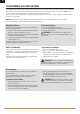
EN WARRANTY AND SERVICE CONTACT INFORMATION Country of Purchase United States of America Horizon Hobby Horizon Service Center (Electronics and engines) Horizon Product Support (All other products) United Kingdom Horizon Hobby Limited Germany Horizon Technischer Service France Horizon Hobby SAS China Horizon Hobby – China Address Phone Number/Email Address 877-504-0233 Online Repair Request: visit www.horizonhobby.com/service 877-504-0233 productsupport@horizonhobby.
© 2012 Horizon Hobby, Inc. The Spektrum trademark is used with permission of Bachmann Industries, Inc. DSM2, AirWare, SimpleScroll, JR, Vibe, X-Plus and Bind-N-Fly are trademarks or registered trademarks of Horizon Hobby, Inc. DSMX is a trademark of Horizon Hobby, Inc., registered in the US. SD Logo is a trademark of SD-3C, LLC US 7,391,320. Other patents pending. www.spektrum-rc.com Created 8/12 28994.