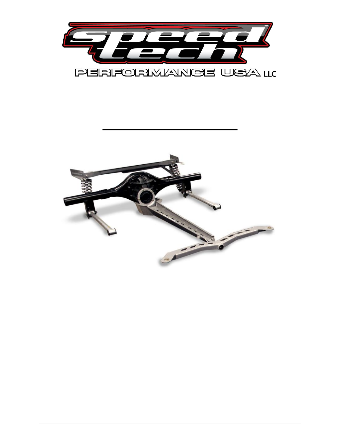
May 6, 2013 Torque Arm Rear Suspension For ’70-81 Camaro/Firebird Installation Instructions The following instructions are intended for professional installers and are guidelines only. Speedtech Performance assumes NO responsibility for the installation of any of its products. All products are intended for off road use only and must be installed by qualified professionals only. Thank you for purchasing your new Speedtech Torque Arm Rear Suspension System.
|Page
Note: This kit requires approximately 30 minutes of welding time to install the upper rear cross member and rear axle mounted support brackets. If you have opted to use your current rear axle rather than ordering a Speedtech prepped rear axle, you will need to remove the existing leaf spring mounts and have your Torque Arm rear axle brackets installed. A guide for bracket location is included with the brackets.
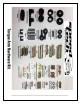
3. Using two ½ x 2” sleeves, the ½”x 4.5” bolts, ½” stover nuts and the black aluminum spacer, install the articulink lower trailing arms into the leaf spring pockets with the small sticker indicating D (driver) or P (passenger) at the front. Do Not completely tighten the bolts at this time as they use stover lock nuts and you will be removing them again later in the installation. The spacers should be installed towards the outside of the car and grease fittings should point downward.
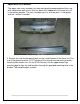
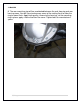
Pictured below is the final spring pocket and trailing arm assembly. Note that the articulating portion of the trailing arm is towards the front, and the spacer is towards the outside of the car. Here is the passenger side Articulink NOTE the swivel end mounts to the front. The bend goes towards the inside of the car.
Upper Main Cross Member The upper main cross member has been designed to accommodate either a car with stock wheel wells or one that has been mini tubbed with the frame rails still in the factory position. The cross member consists of three parts, 2 side plates and the 1 center X member. This photo shows the passenger side. FORWARD >>> 4. Position the side reinforcement plate on the inside/ bottom of the frame rail. The rear of the plate should be 16.
5. Lift the rear X member up and hold it tight to the lower side plates, center the X member in the chassis. The rear edge of the X member should be approximately 21” from the original leaf spring shackle mount center line. See diagram below.
There will be an approximate ¼” gap between the X member and the side plates. This is to accommodate variances in the factory assembly. Make sure the X member is centered and tack weld it in place so that it does not move. Now assemble and test fit the entire rear suspension (see below) in order to make sure everything is square and there is no interference between any parts. Do not skip this part, it is vital to be sure all components fit correctly before the X member is fully welded in.
|Page
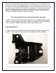
12 Bolt GM 6. The rear mounting ring will be sandwiched between the axle housing and rear housing cover. You will have to clearance some of the casting flash to allow the ring to mount flush. Apply high quality silicone to the housing, set the mounting ring in place, apply silicone and then the cover. Tighten bolts to manufacturer's specs.
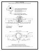
The supplied billet aluminum pinion clamp must be made to fit the pinion snout. Due to the different variations in housings and castings you will need to grind some of the support castings away until the mount fits perfectly. The diagrams supplied below will show where and how much to grind off. When you have the correct fit for the mount, bolt it together using the hardware supplied with the mount.
| P a g e
Shock and Trailing Arm Axle Mounts 7. Using the guidelines supplied with your bracket kit, the trailing arm and pan hard bar mounts need to be welded onto your axle housing. It is very critical that the axle mounting surface is prepped properly and the brackets are aligned correctly and square to the diff as per the instructions. If you have purchased a complete Speed Tech 9” housing then all this will be done for you.
Installing the Rear End and Torque Arm Torque Arm Assembly 9. Install the Torque Arm Delrin bushing on the front pin using the 3/8 bolt and lock washer. You may also want to apply blue loctite to the bolt threads.
Assemble the rear pivot busing and 9/16 x 2” sleeve into the Torque Arm rear mount. Attach Torque Arm to the axle housing using the 9/16 x 3 ¼“ bolt and 9/16” stover nut. Attach the torque arm to the pinion mount. Loosely install the ½ x 2” bolts through the dog bone, then through the torque arm and into the mount.
10. Place your housing/ Torque Arm on a jack and raise it up into position. Install the front pivot pin into the front X member. Install the rear trailing arm ends into the brackets on the axle housing using the 12 x 3 ½“ bolts and nuts. Do not tighten completely. Install the shocks without the springs. Install the pan hard bar. Set the axle housing to your approximate ride height location and check and adjust the pinion angle by shimming between the billet mount and the torque arm.
15. Remove the rear seat. Remove one trailing arm from the rear axle mount and swing it down on the front pivot. Using the two holes in the spring pockets as a guide, drill holes up through the floor. Install two 3/8 x 1 ¼“ bolts through the spring pocket and floor and tighten with the accompanying nuts. Repeat for other side. Reinstall rear seat. 16. Reinstall all components and tighten all hardware, lubricate all grease fittings and fill rear end with oil. 17.
Passenger side pan hard bar adjustment is also for adjusting roll center. For standard setup, adjust the pan hard bar so it is level at ride height with all the finished weight in the car. Trailing arms can be adjusted by turning them in or out to center the wheels in the wheel well. Trailing arms should be set close to level again at ride height and can be adjusted to any hole position to increase or decrease anti squat. Lowering the rear of the arm increases anti squat, helping to increase traction.
For coil over adjustment, use the threaded nuts on the shock only to fine tune the ride height. The springs are only intended to hold the weight of the car. The shock should have approximately 2” of travel both in compression and extension. You should be able to see 2” of shock shaft when the car is at ride height. If you are having to adjust the spring nuts all the way up the shock to raise the vehicle then the springs are too soft for the weight of your car.
Terms and Conditions of Sale 1. Effective January, 2008, supersedes all previous policy statements. Policies are subject to change without notice. Speed tech performance Ltd. is not responsible for printing errors. 2. Speed Tech Performance Ltd. does not endorse, nor recommend modification of vehicles for use on public highways, since warranty or government regulations may be violated.