
Installation Manual

ALPHA® SERIES
SpeedTech Lights, Inc © 2018
Instructions for Mounting, Wiring and Programming
IMPORTANT! To ensure proper installation installers are required to have a good understanding of automotive electronic, systems and proce-
dures for proper installation. When you are drilling into the vehicle’s surfaces, ensure that the area is free of any electrical wires, vehicle uphol-
stery, fuel lines, etc. that could be damaged. All wiring passing through drilled holes should use grommets and silicone sealant to prevent wire
or moisture damage when passing through compartment walls. WARNING! Larger wires and secure or tight connections will ensure longer
service life for your product. It is highly recommended that soldered connections have heat shrink used to protect the connection. Special
attention should be given to the location and method of splicing wiresto make electrical connections to protect these splices from lost power
or connection and corrosion. Insulation displacement connectors are not to be used. To reduce voltage drop, minimize the number of splices in
the wires. The current carrying capacity of wires and fuses will be signicantly reduced under high ambient temperature (e.g. under the hood).
Use SXL type wire in the engine compartment where higher heat resistance is required according to SAE J-3128. All wires should be in accor-
dance with the minimum wire size and other recommendations made by the manufacturer and be protected from hot surfaces and moving
parts. Grommets, cable ties, looms, and other installation hardware should be used to anchor and protect all wiring. Fuses should be properly
sized and located as close to the power take o points as possible to protect the wiring and device. To protect against short circuits, a fuse is
included by STL for all products. Do NOT use a fuse with a higher amp rating than the initial fuse included. Do NOT use Circuit Breaks with STL
Products. Ground terminations should only be made directly to the battery.
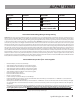
How to Alternate Sync the Alpha® Series Together
• Divide the Alpha® products into two Groups.
• Take all the Red cables from Group 1 and tie them together.
• Take all the Black cables from Group 1 and tie them together.
• Take all the Yellow cables from Group 1 and tie them together.
• Take all the White cables from Group 1 and tie them together.
• Take all the Blue cables from Group 1 and tie them together.
• Connect the Red cables to Power.
• Connect the Black cables to Ground.
• Group 1 is ready for syncing.
• Follow all same procedures for Group 2 as with Group 1.
• Now that both Groups are ready for syncing, take all the Blue cables from Group 1 and hold them to +12VDC for 3 seconds. Half of all
units in Group 1 will light up steady burn.
• Quickly take all the Blue cables from Group 2 and hold them to +12VDC for 5 seconds. You will notice half of all units in Group 2 will light
up steady burn after 3 seconds. Continue to hold it for a total of 5 seconds and you will notice the opposite half of the units will light up
steady burn.
• Once you have programmed both Groups such that Group 1 and Group 2 are all steady burn on opposite sides of each other, disconnect
+12VDC and quickly reconnect +12VDC. NOTE: This step must be done quickly. If any of the Groups go o steady burn and no
longer light up, this step must be repeated. Group 1 and Group 2 units must be half steady burn when you disconnect +12VDC
or else proramming will be incomplete.
• Programming is complete and Group 1 will Single Flash alternatively with Group 2.
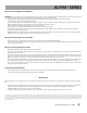
Wire Color Function Wire Color Function
Green
Steady Burn Override
White
Sync
Blue
Sync Program
*Red (Thick)
Positive
Yellow
Flash Pattern
*Black (Thick)
Negative
*
Indicates a main power
cable
NOTE: All cables (except
Negative) contact +VDC