
Owner's manual

Page 10
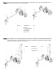
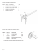
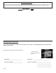
STEP 8: Attach the two fenders (1) to the tank/axle using the four 1/4” NC x 3/4” hex cap bolts (2), the four 1/4” at
washers (3 ) , the four 1/4” lock washers (4) and the four 1/4:” NC hex nuts (5). Tighten
1
2
3
5
ITEM NO. DECSRIPTION QTY.
1 Fender 2
2 1/4” NC Hex Bolt 4
3 1/4” Flat Washer 4
4 1/4” Lock Washer 4
5 1/4” NC Hex Nut 4
4
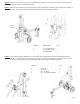
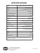
TANK/ENGINE ASSEMBLY BREAKDOWN
O/L- Obtain locally. Common fasteners available through hardware
and farm stores.
ITEM NO. PART NO. DESCRIPTION QTY.
1 O/L 5/16”-18 UNC Nylock Nut 4
2 O/L 5/16” Flat Washer 8
3 O/L 5/16” x 1-1/2” GR5 Hex Bolt 4
4 S39027400 3/4” Return Line Hose 1
5 S39027500 1/2” x 38” Hydraulic Pressue Hose 1
6 S39032000 3/4” NPT x 3/4” Tube 1
7 S39034900 3/4” Hex Nipple 1
8 S39038100 Straight Fitting, 3/4”NPT to 1/2” tube 1
9 S39038900 1” ID Suction Hose 1
10 S39060400 Filter Assembly 1
11 S39073200 Briggs & Stratton 1450/Pump Assy. 1
12 S39031600 Worm Gear Clamp 3
13 S40118800 Tank 1
14 S071022WC Pivot Pin 1
15 O/L 1/2”-3/4” Hairpin Cotter 1
16 S39037500 Dip Stick/Breather Cap 1
17 S390601A0 Filter Element 1
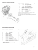
REPLACEMENT PARTS