
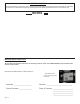
Owner's manual
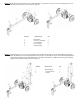
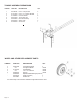

STEP 5: Connect the end of the 1/2” ID x 38” hydraulic pressure hose (1) coming from the tting on the pump to the
tting on the valve. See illustrations below.
STEP 6: Slide one hose clamp (3) on the end of the 3/4” x 56” hydraulic return hose (2 ) that comes from the tting on
the lter. Then connect the hose to the tting on the valve . See illustrations below.
Area of
Detail
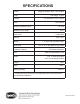
ITEM NO DESCRPTION QTY.
1 1/2” X 38” Pressure Hose 1
2 3/4” x 56” Return Hose 1
3 Worm Gear Clamp 3
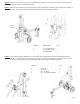
STEP 7: Loosely attach the latch assembly (1) to the bottom side of the beam as shown in the diagram using the
two 1/2” x 1-1/4” GR 5 hex cap bolts (4), the two 1/2” lock washers (3) and the two 1/2” hex nuts (2). Lower
the beam onto the tongue. Center the latch assembly on the tongue and tighten hardware.
ITEM NO. QTY.
1 Beam Lock 1
2 1/2” Hex Nut 2
3 1/2” Lock Washer 2
4 1/2” x 1-1/4” GR5 Hex Cap Bolt 2
Page 9