35 TON VERTICAL/HORIZONTAL LOG SPLITTER MODEL NO. S401635BB Owner’s Manual ASSEMBLY & OPERATING INSTRUCTIONS WARNING: All operators must read this manual before operating this log splitter. Follow the safety instructions in the manual and in decals attached to the product. Failure to do so could result in serious injury or death. LS135-820-0412 Rev.
Table of Contents Important Safety Information................................................................................................................. Page(s) 1-6 Intended Use ......................................................................................................................... 1 Personal Protective Equipment ............................................................................................... 1 Safety Decals .............................
WARNING: Read and thoroughly understand all instructions in this manual and on safety decals before assembling or operating this log splitter. Failure to do so may cause serious injury or death. Do not allow anyone to operate this log splitter who has not read this manual. As with all power equipment, a log splitter can be dangerous if assembled or used improperly. Do not operate this log splitter if you have any questions concerning safe operation.
PART NUMBER: S52062200 LOCATION: TOP OF CYLINDER PART NUMBER: S52062300 LOCATION: STRIPPER PLATE, OPERATOR SIDE PART NUMBER: S52062600 LOCATION: STRIPPER PLATE, NON OPERATOR SIDE PART NUMBER: S52062400 LOCATION: HYDRAULIC TANK LOWER TANK, RIGHT CORNER PART NUMBER: S52062100 LOCATION: TOP OF HYDRAULIC CYLINDER Page 2
GENERAL SAFETY ALWAYS keep the operator’s manual nearby for reference. Reread the manual periodically. ALWAYS keep all bystanders and pets a minimum of 10 feet away from your work area when operating this log splitter. Only the operator is to be near the log splitter during use. NEVER allow adults lacking proper instructions and understanding to operate this log splitter. NEVER actuate the control until all people are clear of the work area.
ALWAYS block the wheels to prevent movement of the log splitter while in operation. KNOW how to stop the log splitter and disengage the controls before operating it. NEVER place hands or feet between the log and splitting wedge during forward or reverse stroke as this could result in serious injury or death. NEVER straddle or step over the log splitter during operation. NEVER reach or bend over the log splitter to pick up a log. NEVER try to split two logs on top of each other.
MAINTENANCE & SAFETY The hydraulic system of your log splitter requires careful inspection along with the mechanical parts. Be sure to replace frayed, kinked, cracked or otherwise damaged hydraulic hoses or hydraulic components. NEVER check for leaks of hydraulic fluid with your hand. Fluid escaping from a small hole can be almost invisible. Escaping fluid under pressure can have sufficient force to penetrate skin causing SERIOUS INJURY or even DEATH.
IMPORTANT NOTE – (spark arrester): As a precautionary measure against possible flying sparks, always take a Class B fire extinguisher with you when operating this log splitter in dry areas. This log splitter is equipped with an internal combustion engine and should not be used on or near any unimproved forest-covered, brush-covered or grass-covered land unless the engine’s exhaust system is equipped with a spark arrester meeting applicable local or state laws (if any).
ASSEMBLY INSTRUCTIONS NOTE: This log splitter was partially assembled at the factory. Refer to the drawings and parts list should it become necessary to disassemble the unit for repair or replacement of parts ITEM NO. 1 2 3 4 5 6 DECSRIPTION QTY. Beam Assembly Beam Lock Assembly Tank Assembly Tire and Wheel Assembly Tongue Assembly Fender 1 1 1 2 1 2 STEP 1: Remove all the components from the shipping container. Inspect each piece for shipping damage.
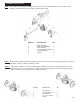
STEP 3: Attach the tongue assembly (5) to the tank assembly (1) using two 1/2” NC x 4-1/2” hex cap bolts (2), two 1/2” lock washers (3) and two 1/2” hex nuts (4). Tighten. ITEM NO. DESCRIPTION QTY. 1 2 3 4 5 Tank Asembly 1/2” NC x 4-1/2 Hex Bolt 1/2” Lock Washer 1/2” NC Hex Nut Tongue Assembly 1 2 2 2 1 STEP 4: Stand the beam (1) up on end. Two people may be needed for this step to ensure safety. Make sure that the beam is stable and on a level surface.
STEP 5: Connect the end of the 1/2” ID x 38” hydraulic pressure hose (1) coming from the fitting on the pump to the fitting on the valve. See illustrations below. STEP 6: Slide one hose clamp (3) on the end of the 3/4” x 56” hydraulic return hose (2 ) that comes from the fitting on the filter. Then connect the hose to the fitting on the valve . See illustrations below. Area of Detail ITEM NO DESCRPTION QTY.
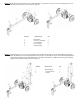
STEP 8: Attach the two fenders (1) to the tank/axle using the four 1/4” NC x 3/4” hex cap bolts (2), the four 1/4” flat washers (3 ) , the four 1/4” lock washers (4) and the four 1/4:” NC hex nuts (5). Tighten ITEM NO. DECSRIPTION 1 2 3 4 5 Fender 2 1/4” NC Hex Bolt 4 1/4” Flat Washer 4 1/4” Lock Washer 4 1/4” NC Hex Nut 4 1 5 2 4 3 REPLACEMENT PARTS TANK/ENGINE ASSEMBLY BREAKDOWN ITEM NO. PART NO.
ENGINE/PUMP ASSEMBLY BREAKDOWN ITEM NO. 1 2 3 4 5 6 7 8 9 10 11 PART NO. O/L O/L O/L O/L S39054500 S39070900 S40034300 S40081800 N/A * N/A* N/A* DESCRIPTION QTY. 5/16”-18 UNC Nylock Nut 5/16” Regular Lock Washer 5/16” x 1-1/4” GR 5 Bolt 5/16” x 1” UNF GR 5 Bolt Briggs & Stratton 1450 Engine 16 GPM Pump 1/4” Sq. x 1-1/2” Square Key Pump Mount Jaw Coupler, 1” Bore Jaw Coupler, 1/2” Bore Coupler Spider 4 4 4 4 1 1 1 1 1 1 1 *Available as complete coupler assembly only.
TONGUE ASSEMBLY BREAKDOWN ITEM NO. 1 2 3 4 5 6 7 8 PART NO. DESCRIPTION QTY. S17280300 S17271600 S17272000 S17290800 S40127200 S40034600 S40032300 S10040300 M10 x 1.5 Nylock Nut M10 x 1.5 x 100mm GR5 Bolt M10 x 1.5 x 120mm GR5 Bolt M10 Flat Washer Tongue with Jack Hitch Ball Assembly Safety Chain Swivel Jack 2 1 1 6 1 1 2 1 WHEEL AND OTHER REPLACEMENT PARTS ITEM NO. PART NO. DESCRIPTION QTY.
OPERATING INSTRUCTIONS WARNING: Read and thoroughly understand all instructions and safety information before operating this log splitter. Failure to do so may cause serious injury or death. Do not allow anyone to operate this log splitter who has not read this manual. As with all power equipment, a log splitter can be dangerous if assembled or used improperly. Do not operate this log splitter if you have doubts or questions concerning safe operation.
CAUTION: TURN FUEL SHUT OFF VALVE TO THE “OFF” POSITION PRIOR TO TOWING.FAILURE TO DO SO MAY RESULT IN FLOODING THE ENGINE. NOTE: The engine maximum governed speed is preset at the factory at 3600 RPM no load speed. When splitting wood the throttle should be set at the maximum speed to develop the horsepower required for the pump. OPERATION WARNING: See safety information related to operation of the log splitter on page 3 and 4 of this manual.
MAINTENANCE 1) Consult the operating and maintenance instructions of the engine manufacturer for engine care and maintenance. 2) Always check the oil level of the hydraulic reservoir before operation. Operating the log splitter without an adequate oil supply will cause severe damage to the pump. 3) Change the oil filter after the first 25 hours of operation. There after change the oil filter every 100 hours or seasonally, whichever comes first.
IMPORTANT NOTICE We, the manufacturer, reserve the right to change the product and/or specifications in this manual without notification. The manual is for information usage only and the pictures and drawings depicted herein are for reference only. NOTES Warranty Repair and Service Do not return this product to the store for warranty issues or repair. Call 1-800-525-8322 for the location of the nearest service center. Record the information below for future reference.
SPECIFICATIONS Engine Pump Cylinder Valve Maximum Splitting Force* Maximum Log Length Cycle Time* Briggs & Stratton 305cc 1450 Engine Two-Stage, 16 gpm 5 in. Diameter x 24 in. Stroke Auto-Return 35 Tons 26 in. 14 Seconds Wheels 4.80 x 8 in. Wedge 7 in. High with Spreader Wings Beam Size Hydraulic Capacity 8 in. x 10 in. with Built-In Log Cradle 6.5 Gallons Maximum Filter Spin-On Replaceable Filter Height 72 in. in Vertical Position 42 in. in Horizontal Position Length 78 in. Width 49 in.