
Manual

Page 9
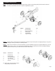
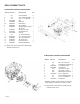
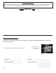
STEP 5: Connecttheendofthe1/2”IDx38”hydraulicpressurehose(1)comingfromthettingonthepumptothe
ttingonthevalve.Seeillustrationsbelow.
STEP 6: Slideonehoseclampontheendofthe3/4”x56”hydraulicreturnhose(2)thatcomesfromthettingonthe
lter.Thenconnectthehosetothettingonthevalve.Tightenhoseclamp.Seeillustrationsbelow.
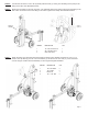
DETAIL A
SCALE 1:3
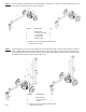
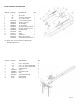
STEP 7: Attach the latch (3) to the bottom side of the beam as shown in the diagram using the two 1/2” x 1-1/4”
Grade 5 hex cap bolts (4), the two 1/2” lock washers (1) and the two 1/2” hex nuts (2 ). Lower the beam
onto the tongue. Position the latch assembly on the tongue and tighten hardware.
ITEM NO. DESCRIPTION QTY.
1 1/2” Lock Washer 2
2 1/2” Hex Nut 2
3 Beam Lock 1
4 1/2” x 1-1/4” Bolt 2
Area of
Detail
Page 9
ITEM NO. DESCRIPTION QTY.
1 1/2” X 38” Pressure Hose 1
2 3/4” x 56” Return Hose 1
3 Worm Gear Clamp 3
4