
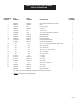
Manual

IMPORTANT: The gear box is shipped without lubricant. Fill the top hole with EP 90 lubricant or the equiva-
lent.
Approximately 1.75 quarts of the lubricant is enough to lubricate the gears and bearings. A
greateramountwillnotharmthegearbox.Donotlltooverowpointasthismay
damage the seals.
STEP 1: Becertainthatthegearboxhasadequatelubrication.Checktheoillevelaftereveryftyhours
of use.
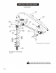
STEP 2: Attach the boom (1) to the top link mounting bracket on the tractor using a top link pin and a
lynch pin (not provided) through the swivel ball at the bottom of the boom. The ball accepts
either category 1 or 2 pins.
STEP 3: Connectthe“A”frame(5)tothetractor’s3-pointliftarmsusingthe7/8in.pullpinswithnut
and
lockwasher (7) as shown in the drawing. Attach the “A” frame (5) to the boom (1) after selecting
the desired hole (for angle adjustment) using the “A” frame pin (6) and lynch pin (4).
STEP 4: Attach the gear box (10) to the boom (1) using the boom pin supplied with the gear box. When
in place secure with the cotter pins provided. NOTE: Input shaft shield (9) and output
shaft shield (8) are already attached to the gear box.
STEP 5: Attach the auger (18,19,20, 25 or 26 ) to the output shaft on the bottom of the gear box (10)
using the1/2in.hexcapscrews(15),1/2in.lockwashers(16)and1/2in.hexnuts(17).
Tighten the nuts.
STEP 6: Attach the driveline (11)tothegearboxinputshaftusingthe3/8in.grade5hexcapscrew(12),
the3/8in.lockwasher(13)andthe3/8in.NChexnut(14).Tightenthehexnut.Insertthe1/4
in.x3/8in.setscrew(24)fromthehardwarekitintheholeontheyokethatalignswiththe
3/16 in.grooveonthegearboxinputshaft.Tightenloosely.
ATTENTION: THE3/8IN.HEXCAPSCREWPROVIDESSHEARPROTECTION.USEAGRADE5
3 IN. BOLT ONLY TO AVOID DAMAGE TO THE GEAR BOX OR AUGER.
IMPORTANT: The universal joint should be greased with a good grade chassis lube every week. At the
beginning of each season grease the sliding driveshaft members with a moly grease. All
diggers are equipped with quick-detach universal joints on the power-take-off end for a
1-3/8in.splinedshaft.
STEP 7: Attach the tractor end of the driveline (11) to the tractor PTO shaft. Push in the spring-loaded
pin
in the splined yoke and slip it on the splined PTO shaft of the tractor. Release the pin and
pushuntilitlockssecurelyinplace.Itwillbenecessarytoobtaina1-1/8in.to1-3/8in.sleeve
splineadapterifyourtractorPTOshafthasa1-1/8in.spline.
STEP 8: Attach and secure the lower chain on the driveline to the boom (1). Attach the upper chain to
the hole on the gear box shield (9).
STEP 9: Check all nuts and bolts for tightness. Stabilizers should be kept tight to avoid side sway of the
digger.
Page 5
ASSEMBLY INSTRUCTIONS
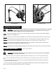
NOTE: See illustration A for reference in assembling the digger and mounting it to the tractor.
Note that the boom angle can be adjusted on your tractor for proper digging and ground
clearance by moving the “A” frame to a different mounting hole as shown in illustration B.
NOTE: Whenthe7/8in.diameterpullpinsinthe“A”framearetoosmallfortheholesinthelift
arms,bushingsshouldbeusedtoobtainapropert