HEAVY DUTY POST HOLE DIGGER PD24460 (24046000) OWNER’S MANUAL ASSEMBLY & OPERATING INSTRUCTIONS THIS SAFETY ALERT SYMBOL IDENTIFIES IMPORTANT SAFETY MESSAGES IN THIS MANUAL. FAILURE TO FOLLOW THIS IMPORTANT SAFETY INFORMATION MAY RESULT IN SERIOUS INJURY OR DEATH.
Table of Contents Page(s) Important Safety Information ................................................................................................ 1-4 Intended Use .............................................................................................................. 1 Personal Protective Equipment ................................................................................. 1 Safety Decals .........................................................................
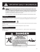
WARNING: Read and thoroughly understand all instructions and safety information before assembling or operating this post hole digger Failure to do so may cause serious injury or death. Do not allow anyone to operate this post hole digger who has not read this manual. As with all power equipment a post hole digger can be dangerous if assembled or used improperly. Do not operate this post hole digger if you have doubts or questions concerning safe operation.
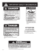
PART NUMBER: DL52020200 LOCATION: UPPER RIGHT SIDE OF BOOM PART NUMBER: DL51019200 LOCATION: PTO DRIVE SHAFT SHIELD PART NUMBER: DL51011900 LOCATION: PTO DRIVE SHAFT PART NUMBER: DL52020300 LOCATION: UPPER LEFT SIDE OF BOOM AND PART NUMBER: DL52020400 LOCATION: BOTH SIDES OF GEAR BOX SHIELD Page 2
PART NUMBER: DL52020500 LOCATION: TOP END OF AUGER NOTE: IF THE OUTPUT SHAFT GUARD MENTIONED IN THE ABOVE DECAL IS MISSING ,YOU MAY ORDER A REPLACEMENT BY CALLING US AT 1-800-525-8322. GENERAL SAFETY AND PREPARATION ALWAYS make sure that anyone else who operates this post hole digger has read and understood the contents of the owner’s manual and all safety decals on the product.
ALWAYS make sure that the tractor brake is set before digging a hole. ALWAYS keep hands, feet and clothing away from power-driven parts during operation. NEVER manually position the auger or manually force the auger into the ground. ALWAYS make sure that the tractor engine is shut off and the PTO drive is disengaged before leaving the tractor seat. NEVER move the tractor with the power-take-off in the ON position. NEVER exceed 540 RPM PTO operating speed.
ASSEMBLY INSTRUCTIONS IMPORTANT: lent. The gear box is shipped without lubricant. Fill the top hole with EP 90 lubricant or the equiva- Approximately 1.75 quarts of the lubricant is enough to lubricate the gears and bearings. A greater amount will not harm the gear box. Do not fill to overflow point as this may damage the seals. STEP 1: Be certain that the gear box has adequate lubrication. Check the oil level after every fifty hours of use.
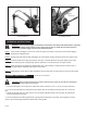
Angle Adjustment Angle Adjustment ILLUSTRATION A ILLUSTRATION B OPERATING INSTRUCTIONS WARNING: Read and thoroughly understand all instructions and safety information before operating this post hole digger Failure to do so may cause serious injury or death. Do not allow anyone to operate this post hole digger who has not read this manual. STEP 1: After mounting the digger to the tractor, lower the auger point slowly to the ground at the desired digging angle before engaging power.
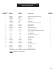
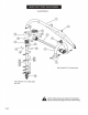
MODEL POST HMRTS HEAVY DUTY POST BREAKDOWN HOLE DIGGER PARTS BREAKDOWN REFERENCE NUMBER SKU NUMBER PART NUMBER DESCRIPTION 24046000 PD24460 Heavy Duty Post Hole Digger less Auger 1 24086100 PD24861 Boom 1 4 *07090100 P791 7/16 in. Lynch Pin 1 5 24086000 PD24860 "A" Frame 1 6 *07070100 P771 "A" Frame Pin 1 7 *07020800 P728 7/8 in.
CUTTING EDGES AND POINT PARTS BREAKDOWN REFERENCE NUMBER 1 SKU NUMBER PART NUMBER 24122200 PD241222 2 O/L O/L NUMBER REQUIRED* DESCRIPTION Cutting Edge varies by auger 1/2 in.-1 in. UNC Carriage Bolt 1 per cutting edge 3 O/L O/L 1/2 in. UNC Lock Nut 1 per cutting edge 4 O/L O/L 1/2 in. x 3 -1/2 in. Bolt 1 O/L 1/2 in. Lock Nut 1 Auger Point 1 5 O/L 6 24121900 PD241219 O/L- Obtain locally. Common fasteners available through hardware and farm stores.
DRIVELINE PARTS BREAKDOWN REFERENCE NUMBER SKU NUMBER PART NUMBER DESCRIPTION NUMBER REQUIRED 1 24112100 PD241121 Half Outer Yoke 1 2 24112200 PD241122 Yoke Assembly (tractor) 1 2A 24112300 PD241123 Push Pin Kit 1 3 24112400 PD241124 Cross Assembly 2 4 24112500 PD241125 Outside Tube with Yoke 1 5 24112600 PD241126 Half Inner Shaft 1 6 24112700 PD241127 Inside Tube with Yoke 1 7 24112800 PD241128 Yoke Assembly (implement) 1 8 24112900 PD241129 Half Outer Guard
SPECIFICATIONS Tractor Category Category 1 and Category 2 Gear Box Special alloy pinion gears and tapered roller bearings on both sides of each gear Driveline Equipped with quick-tach yoke to fit standard 6-spline PTO (completely shielded) Augers 6 in., 9 in., 12 in. , 18 in. and 24 in. (sold separately) Cutting Edges Replaceable, carbide (sold separately) Point Spiral tip (sold separately) Boom 3-1/4 in. in. O.D.
NOTES Model No.
Part No.