
User guide

Micro800™ 4 Ch Universal Analog Input Module 14
Publication 0100189-02 Rev. A
Voltage Accuracy
System accuracy at 25ºC (4 and 17 Hz filters)
± 40 µV maximum for ± 50 mV inputs
± 40 µV maximum for ± 100 mV inputs
± 6 mV maximum for 0-5 V inputs
± 20 mV maximum for 0-10 V inputs
± 20 mV maximum for ±10 V inputs
System accuracy at -20-65ºC (4 and 17 Hz filters)
± 80 µV maximum for ± 50 mV inputs
± 80 µV maximum for ± 100 mV inputs
± 12 mV maximum for 0-5 V inputs
± 40 mV maximum for 0-10 V inputs
± 40 mV maximum for ± 10 V inputs
Current Accuracy
System accuracy at 25ºC (4 and 17 Hz filters)
± 50 µA maximum for 0-20 mA inputs
± 50 µA maximum for 4-20 mA inputs
System accuracy at -20-65ºC (4 and 17 Hz filters)
± 120 µA maximum for 0-20 mA inputs
± 120 µA maximum for 4-20 mA inputs
RTD Accuracy
System accuracy at 25ºC (4 and 17 Hz filters)
± 0.7 ºC for 1000 Platinum 385 and 3916
± 3.1 ºC for 100 Platinum 3916
± 3.4 ºC for 100 Platinum 385
System accuracy at -20-65ºC (4 and 17 Hz filters)
± 1.2 ºC for 1000 Platinum 385 and 3916
± 4.7 ºC for 100 Platinum 3916
± 5.1 ºC for 100 Platinum 385
Resistance Accuracy
System accuracy at 25ºC (4 and 17 Hz filters)
± 1.5 for 3000 range
System accuracy at -20-65ºC (4 and 17 Hz filters)
± 2.5 for 3000 range
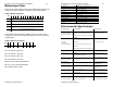
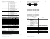
Repeatability (at 25ºC)
4 Hz filter 17 Hz filter 60, 240 & 470 Hz
filters
1
Type J
± 0.2 ºC ± 0.4 ºC ± 1 ºC
Type K (-200ºC to 1370ºC)
± 0.2 ºC ± 0.4 ºC ± 2 ºC
Type K (-270ºC to -200ºC)
± 2 ºC ± 3.5 ºC ± 10 ºC
Type T (-190ºC to 400ºC)
± 0.2 ºC ± 0.4 ºC ± 2 ºC
Type T (-270ºC to -190ºC)
± 1 ºC ± 1.5 ºC ± 8 ºC
Type E (-200ºC to 1000ºC)
± 0.2 ºC ± 0.4 ºC ± 2 ºC
Type E (-270ºC to -200ºC)
± 1 ºC ± 1.5 ºC ± 8 ºC
±50 mV, ±100 mV
± 20 µV ± 22 µV ± 40 µV
0-5V, 0-10V, +/-10V
± 1.5 mV ± 1.8 mV ± 6 mV
0-20 mA, 4-20 mA
± 3 µA ± 4 µA ± 15 µA
RTD, Platinum 385, 3916
± 0.3 ºC ± 0.4 ºC ± 2 ºC
Resistance
± 0.2 ± 0.3 ± 2
CMRR
84 dB minimum at 50 and 60 Hz for 4 Hz and 17 Hz
filters
NMRR
4 Hz filter 72dB minimum at 50 and 60 Hz
17 Hz filter 62dB minimum at 50 and 60 Hz
Crosstalk
-70dB maximum
Cable resistance (applies only to 3-
and 4-wire RTD & resistance
measurements)
25 maximum
Input bias current
Less than ± 2.5 µA steady state for ±10V inputs, less
than 1.75A for all other voltage and TC inputs. Less
than ± 40 µA peak for all voltage and TC input
configurations.
Current input impedance
249 ± 0.1%, 10 PPM/°C
Input protection
Voltage Mode ± 30 VDC continuous.
Current Mode 28 mA continuous.
Power source
3.3 VDC & 24 VDC from backplane, 30mA max from
each
Channel to Channel Isolation
None
1
These filters do not reject 50/60 Hz. Repeatability for these filters is strongly dependent
on how much 50/60Hz noise is in the system.
Micro800™ 4 Ch Universal Analog Input Module 11
Publication 0100189-02 Rev. A
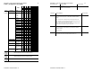
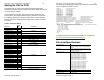
Table 5 (Under/Over Range Status)
Bit 7 6 5 4 3 2 1 0
O3 O2 O1 O0 U3 U2 U1 U0
Bit 0 is for channel 0 under range indication
Bit 1 is for channel 1 under range indication
Bit 2 is for channel 2 under range indication
Bit 3 is for channel 3 under range indication
Bit 4 is for channel 0 over range indication
Bit 5 is for channel 1 over range indication
Bit 6 is for channel 2 over range indication
Bit 7 is for channel 3 over range indication
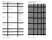
Table 6 (General Module Status)
Bit
Number
Description Notes
0-1
These 2 bits define module
operation mode,
0: Idle: Module is ready to RUN,
and I/O is off.
1: RUN: Module is under RUN,
and I/O is on.
2: Error: Error happens, and I/O is
off.
3: Busy: Module is busy, cannot go
to RUN, and I/O is off.
2
This bit defines module user
interrupt mode,
0: User Interrupt is disabled.
1: User Interrupt is enabled.
The IF4U does not support this
functionality; this bit is always off (0).
3 Reserved
4 SW Error
Trigger condition – Watchdog timer
triggered.
5 ADC Error
Trigger condition – ADC
communication stops or ADC has not
sampled data for long period of time.
6 Calibration Error
Trigger condition – blank calibration or
calibration checksum error.
7 Configuration Error
Wrong bits set in channel
configuration.