
User Manual


Compact IO™ Isolated HART Analog Output Module
User’s Manual 03 00217-03 Rev. A
7-8
Table 7-5 (HART Packet 4)
Tag Name Data Type
Style
Description
If4i h0 P ack et4 P ack et 4 [ 4,1] NA Two di m ensional array c ontaini ng
packet 4 data for all 4 channel s .
If4ih0Packet4[X,0].HartChannelID INT BI N
Bits 0 to 3: Channel number (0 – 3 ).
Bit 4 : S earching/Initi a lizing HART devi ce
Bit 5: HART c ommunica tion failure or
device not found
Bit 6: P a ss- t hrough message pending
(ready)
Bit 7: Unused (0)
Bits 8 to 10: Packet ID
Bit 11 thr ough 15: Unused
If4ih0Packet4[X,0].Date SI N T[3] DEC
Stor e d da te in the field device
If4ih0Packet4[X,0].FinalAssemblyNumber SINT[3] DEC
The final assembly number is used for
identi fyi ng the material s and electroni cs
that compr ise the fiel d device.
If4ih0Packet4[X,0].ExtendedStatus SINT[24] DEC
The extended status retur ned by H ART
command 48
If4ih0Packet4[X,0].Pad SINT[3] DEC
Pad 32 bit alignment
1
X represents the module channel number (0 to 3)
Note: Not all of the HART data that is returned by the process outlined in Figure 7-4
(Auto Acquisition Flow) gets passed to the packets. In order to access the data that is
not passed to the packets, you must execute the appropriate HART message using the
pass-through co mmand, which will be discussed later in this chapter.
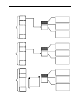
The ladder determines which packet to copy the data to, by monitoring the state of bits 0,
1, 2 and 8, 9, 10, found in the first two bytes of the OF4IH0Input.HartData tag. Bits 0, 1,
2 determine the current channel being scanned and bits 8, 9, and 10 determine the packet
number. The ladder example, shown in Figure 7-4, performs this operation.