
User Manual


Chapter 6: Module Data, St at us, and C on fig urat i o n
User’s Manual 03 00217-03 Rev. A
6-7
Note: Not all controllers support this function. Refer to your controller’s user manual
for more details.
SV0...SV3 (Slot Variables 0 to 3)
Enables HART slot variables 0 through 3 for the selected channel.
Note: Slot variabl es are not sup po rt ed by a l l HART devices.
Note: Slot codes must be enabled in sequential order. For example, SV0 (Enabled),
SV1 (Disabled), and SV2 (Enabled), is not a v alid configuration. In this case, all three
slot variables would be enabled.
Reserved
Must be set to Zero
EC (Enable Channel)
This bit allows the user to enable or disable the channel.
6.3.13 Channel X
1
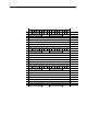
Output Type and Data Format (Words 1, 9, 17, 25)
This section of the configuration allows the user to define the output type (i.e. 0 to 20mA
or 4 to 20 mA) and the data format for the associated channel. See table below.
Table 6-4 (Output Type and Data Format)
1514131211109876543210
0 to 20mA
000
4 to 20mA
001
Reserved
Se t To Z er o
00000
Raw /Proportional
000
Engineering Units
001
Sc aled for PID
010
Perc ent Range
011
Reserved
Se t To Z er o
00000
To S e le c t
M ak e thes e bit s ettings
Output Type
Data Type
Output Type
Allows the user to configure the output type and range for the associated channel.
Note: To enable HART you must select the 4 to 20 mA range.
Reserved
Reserved for future expansion an d should be set to zero.