
User Manual


Compact™ IO Isolated HART Analog Output Module
User’s Manual 03 00217-03 Rev. A
1-2
Section 1.3
Hardware
Features
The module contains a removable terminal block. Each channel has a dedicated ground
which is isolated from the remaining channels by 500VDC.
Do not short the channel grounds together unless you plan to remove the
channel to channel isolation.
Module configur ation is done via the controller’s programming software. In addition,
some controllers support configuration via the user program. In either case, the module
configuration is stored in the memory of the controller. Refer to your controller’s user
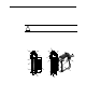
manual for more information. The illustration below shows the module’s hardware
features.
Figure 1-1
Item Description
1 bus lever
2a upper panel m ou nti ng tab
2b lower panel mounting tab
3 module status LED
4 module door with terminal identification label
5a movable bus connector (b us interface) with female pins
5b stationary bus con necto r (b us interface) wit h male pins
6 nameplate label
7a upper tongue-and-gr oo ve slots
7b lower tongue -and-groove sl ots
8a upper DIN rai l latch
8b lower DIN rail latch
!
Attention
5a
9
5b
6
7a
7b
8b
7b
8a
7a
OK
HART
10a
10b
4
10
2b
3
2a
1
DAN GE R
Do Not Remove RTB Under
Power Unless Area is No n-
Hazardous
Ensure Adjacent Bus
Lever i s Unlatched/
Latched Before/Af ter
Removing/Inserting
Module
OK
HART