
Instruction Manual


Chapter 6: 1756sc-OF8H Channel Configuration, Data, and Status 61
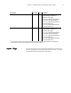
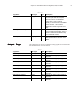
Table 6.2d
Tag Name Data Type Style Description
Of8h0Input.CST DINT[2] DEC This is the timestamp taken at the
time the input data was sampled,
which is in terms of coordinated
system time. This is a 64 bit
quantity in microseconds coordinated
across the rack. This must be
addressed in 32 bit segments as an
array.
Of8h0Input.TimeStamp INT DEC This is the timestamp taken at time
the input data was sampled, which is
shown in milliseconds relative solely
to the individual module.
Of8h0Input.HartData SINT[40] DEC An array of 40 bytes which contains
HART packet data for the entir more
details.
Output Output
Output Output
Output
TT
TT
T
aa
aa
a
gsgs
gsgs
gs
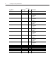
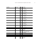
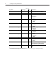
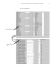
The output tags are used to control the analog signals for each channel.
See the table below for more details.
Table 6.3
Tag Name Data Type Style Description
Of8h0Output Of8hOutputBlock NA Module output data
Of8h0Output.Ch0Data FLOAT REAL Controls the analog output signal for
channel 0
Of8h0Output.Ch1Data FLOAT REAL Controls the analog output signal for
channel 1
Of8h0Output.Ch2Data FLOAT REAL Controls the analog output signal for
channel 2
Of8h0Output.Ch3Data FLOAT REAL Controls the analog output signal for
channel 3
Of8h0Output.Ch4Data FLOAT REAL Controls the analog output signal for
channel 4
Of8h0Output.Ch5Data FLOAT REAL Controls the analog output signal for
channel 5
Of8h0Output.Ch6Data FLOAT REAL Controls the analog output signal for
channel 6
Of8h0Output.Ch7Data FLOAT REAL Controls the analog output signal for
channel 7