
Instruction Manual

14 ControlLogix
™
Analog HART Modules
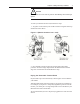
- connect to devices keeping the leads short
Important: If noise persists, try grounding the opposite end of the cable,
instead (Ground one end only.)
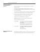
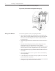
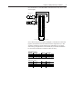
Terminal Block Layout
The following figure shows the general terminal block layout. The input
signal type will determine which pins are used.
1
3
5
7
9
11
13
15
17
19
2
4
6
8
10
12
14
16
18
20
VOUT-0
IOUT-0
RTN
VOUT-1
IOUT-1
VOUT-2
IOUT-2
VOUT-3
IOUT-3
RTN
VOUT-4
IOUT-4
RTN
VOUT-5
IOUT-5
VOUT-6
IOUT-6
RTN
VOUT-7
IOUT-7
RTN
IN4+
IN4-
IN5+
IN5-
RTN
IN6+
IN6-
IN7+
IN7-
IN0+
IN0-
IN1+
IN1-
IN2+
IN2-
IN3+
IN3-
I RTN-0
NC
I RTN-1
NC
I RTN-2
NC
I RTN-3
NC
RTN
I RTN-4
NC
I RTN-5
NC
RTN
I RTN-6
NC
I RTN-7
NC
2
4
6
8
10
12
14
16
18
20
22
24
26
28
30
32
34
36
1
3
5
7
9
11
13
15
17
19
21
23
25
27
29
31
33
35
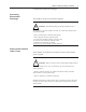
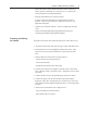
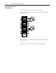
Wiring Inputs to the
IF8H Module
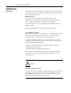
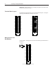
Voltage Inputs - Voltage inputs use the terminal block pins labelled IN+#
and IN-#.
Note: All terminals marked RTN are connected internally.
RTN
IN4+
IN4-
IN5+
IN5-
RTN
IN6+
IN6-
IN7+
IN7-
IN0+
IN0-
IN1+
IN1-
IN2+
IN2-
IN3+
IN3-
I RTN-0
NC
I RTN-1
NC
I RTN-2
NC
I RTN-3
NC
RTN
I RTN-4
NC
I RTN-5
NC
RTN
I RTN-6
NC
I RTN-7
NC
2
4
6
8
10
12
14
16
18
20
22
24
26
28
30
32
34
36
1
3
5
7
9
11
13
15
17
19
21
23
25
27
29
31
33
35
+V
- V
Voltage Input