Publication 0300146-08 Rev. J Isolated-Circuit Discrete Input and Output Modules (Cat. No.
Installation Instructions Isolated-Circuit Discrete Input and Output Modules Preface In addition to providing module specifications, this document tells you how to: • install your module into the SLC 500™ chassis • wire field devices to your module • interpret your module’s LED indicators • check for blown fuses (1746sc-OAP8I only) • get technical assistance Please read all the information in this publication before installing these products.
Installation Instructions Isolated-Circuit Discrete Input and Output Modules 2 2
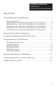
Installation Instructions Isolated-Circuit Discrete Input and Output Modules Table Of Contents General Information And Specifications .........................................................4 General Specifications .......................................................................................... 4 -IA8I Specifications, On/Off-State Voltage Range, & Circuit Diagram .............. 6 -IB8I Specifications, On/Off-State Voltage Range, & Circuit Diagram ..............
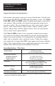
Installation Instructions Isolated-Circuit Discrete Input and Output Modules General Information And Specifications This module is designed exclusively to mount Allen-Bradley 1746 I/O racks for use with Allen-Bradley SLC500 fixed and modular systems. The 1746scIA8I, IB8I, -IC8I, and -IM8I feature 8 isolated-circuit inputs, each with its own common. These modules also feature broad operating ranges for increased versatility.
Installation Instructions Isolated-Circuit Discrete Input and Output Modules As noted in the previous table, these 1746sc-Series modules provide 1500 V point-to-point isolation. This point-to-point isolation means: • shorts, overloads, or noise on one circuit won’t affect devices on other circuits. • different power sources can be connected to the same module without damaging components due to excessive voltage differences between points.
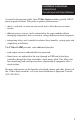
Installation Instructions Isolated-Circuit Discrete Input and Output Modules 1746sc-IA8I Specifications Number of Inputs 8 Points per Common 1 (individually isolated) Voltage Category 100/120 Vac @ 50/60 Hz 100/120 Vdc, sink or source Operating Voltage 80 to 150 Vac @ 47 to 63 Hz 85 to 170 Vdc Nominal Input Current 16 mA @ 120 Vac, 60 Hz 2.5 mA @ 120 Vdc Input Inrush Current (maximum) 0.
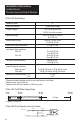
Installation Instructions Isolated-Circuit Discrete Input and Output Modules 1746sc-IB8I Specifications Number of Inputs 8, sink or source Points per Common 1 (individually isolated) Voltage Category 24 Vdc Operating Voltage ±11.5 to 32 Vdc Nominal Input Current 12 mA @ 24 Vdc Input Signal Delay (maximum) Off to On On to Off 0.5 ms @ 24 Vac 1 ms @ 24 Vac Off-State Current (maximum) 1.8 mA @ 4.5 Vac ➀ Power Dissipation (maximum) ➁ Watts per point Total Watts ➂ 6.6 W @ 240 Vac/dc 0.
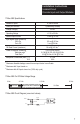
Installation Instructions Isolated-Circuit Discrete Input and Output Modules 1746sc-IC8I Specifications Number of Inputs 8, sink or source Points per Common 1 (individually isolated) Voltage Category 48 Vdc Operating Voltage ± 30 to 60 Vdc Nominal Input Current 10 mA @ 48 Vdc Input Signal Delay (maximum) Off to On On to Off 0.5 ms @ 48 Vdc 1 ms @ 48 Vdc Off-State Current (maximum) 1.8 mA @ 9.5 Vac ➀ Power Dissipation (maximum) ➁ Watts per point Total watts ➂ 4 W @ 120 Vac/dc 0.
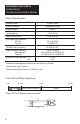
Installation Instructions Isolated-Circuit Discrete Input and Output Modules 1746sc-IM8I Specifications Number of Inputs 8, sink or source Points per Common 1 (individually isolated) Voltage Category 200/240 Vac @ 50/60 Hz 200/240 Vdc Operating Voltage 160 to 264 Vac @ 47 to 63 Hz 170 to 265 Vdc Nominal Input Current 13.5 mA @ 240 Vac, 60 Hz 2.5 mA @ 250 Vdc Input Inrush Current (maximum) 0.
Installation Instructions Isolated-Circuit Discrete Input and Output Modules 1746sc-OAP8I Specifications Number of Outputs 8 triac Points per Common 1 Module Location 1746 I/O chassis Voltage Category 120/240 Vac @ 50/60 Hz Operating Voltage 74 to 276 Vac @ 47 to 63 Hz Output Current Rating Per Point 1.
Installation Instructions Isolated-Circuit Discrete Input and Output Modules Important Pre-Installation Considerations This module is shipped in a static-shielded container to guard against electrostatic discharge damage.
Installation Instructions Isolated-Circuit Discrete Input and Output Modules Installing Your Module Into The SLC 500 Chassis ! WARNING EXPLOSION HAZARD When in hazardous locations, turn off power before replacing or wiring modules. Failure to observe this precaution can cause equipment damage, severe personal injury, or death. ! WARNING POSSIBLE EQUIPMENT OPERATION AND DAMAGE Always remove power from the I/0 chassis backplane and terminal block before removing or installing an I/O module.
Installation Instructions Isolated-Circuit Discrete Input and Output Modules 1.Turn off power to the I/O chassis. 2.Align the circuit board of your module with the card guides at the top and bottom of the chassis 3.Slide your module into the chassis until both top and bottom retaining clips are secure. Apply firm even pressure on your module to attach it to its backplane connector. Never force your module into the slot. Cover all unused slots with the Card Slot Filler, Allen-Bradley part 1746-N2.
Installation Instructions Isolated-Circuit Discrete Input and Output Modules Wiring Field Devices To Your Module For UL and C-UL compliance, power, input, and output (field device) wiring must be in accordance with Class I, Division 2, wiring methods [Article 5014 (b) of the National Electrical Code, NFPA 70] and in accordance with the authority having jurisdiction. In addition, peripheral equipment must be suitable for the location in which it is used.
Installation Instructions Isolated-Circuit Discrete Input and Output Modules To wire field devices to your module, follow these steps: 1. Turn off power to the I/O chassis. 2. Optional: Remove the supplied 18-position red terminal block from the module. To remove the terminal block, unscrew the two retaining screws at the top and bottom of the terminal block, and pull the terminal block loose. 3.
Installation Instructions Isolated-Circuit Discrete Input and Output Modules In addition, for the 1746sc-IA8I, -IB8I, -IC8I, and -IM8I only, you must install a ferrite on the SLC 500 power line. You may use either a clam-shell type (Steward part 28B2029-0A0 or equivalent) or a ring type (Steward part 28B2400-000 oivalent). If you use the ring type, loop the cable through at least once.
Installation Instructions Isolated-Circuit Discrete Input and Output Modules 1746sc-IA8I Isolated-Circuit 100/120 V ac/dc Inputs (8) VS0 L1 or +VDC 100/120 V ac/dc VAC/VDC 0+ VS1 L1 or +VDC VAC/VDC 1+ VS2 L1 or +VDC VAC/VDC 2+ VS3 L1 or +VDC VAC/VDC 3+ IN 0– IN 1– IN 2– IN 3– E-GND E-GND VS4 L1 or +VDC VAC/VDC 4+ VS5 L1 or +VDC VAC/VDC 5+ VS6 L1 or +VDC VAC/VDC 6+ VS7 L1 or +VDC VAC/VDC 7+ Alternative input device location VS0 L2 or DC COM 0 VS1 L2 or DC COM 1 VS2 L2 or DC COM 2 VS3 L2
Installation Instructions Isolated-Circuit Discrete Input and Output Modules 1746sc-IB8I Isolated-Circuit 24 Vdc Inputs (8) VS0 +VDC 24 Vdc* VDC 0+ VS1 +VDC VDC 1+ VS2 +VDC VDC 2+ VS3 +VDC VDC 3+ IN 0– IN 1– IN 2– IN 3– E-GND E-GND VS4 +VDC VDC 4+ VS5 +VDC VDC 5+ VS6 +VDC VDC 6+ VS7 +VDC VDC 7+ Alternative input device location VS0 DC COM 0 VS1 DC COM 1 VS2 DC COM 2 VS3 DC COM 3 Rack mounting bolt IN 4– VS4 DC COM 4 IN 5– VS5 DC COM 5 IN 6– VS6 DC COM 6 IN 7– VS7 DC COM 7 Note —
Installation Instructions Isolated-Circuit Discrete Input and Output Modules 1746sc-IC8I Isolated-Circuit 48 Vdc Inputs (8) VS0 +VDC 48 Vdc* VDC 0+ VS1 +VDC VDC 1+ VS2 +VDC VDC 2+ VS3 +VDC VDC 3+ IN 0– IN 1– IN 2– IN 3– E-GND E-GND VS4 +VDC VDC 4+ VS5 +VDC VDC 5+ VS6 +VDC VDC 6+ VS7 +VDC VDC 7+ Alternative input device location VS0 DC COM 0 VS1 DC COM 1 VS2 DC COM 2 VS3 DC COM 3 Rack mounting bolt IN 4– VS4 DC COM 4 IN 5– VS5 DC COM 5 IN 6– VS6 DC COM 6 IN 7– VS7 DC COM 7 Note —
Installation Instructions Isolated-Circuit Discrete Input and Output Modules 1746sc-IM8I Isolated-Circuit 200/240 V ac/dc Inputs (8) VS0 L1 or +VDC 200/240 V ac/dc VAC/VDC 0+ VS1 L1 or +VDC VAC/VDC 1+ VS2 L1 or +VDC VAC/VDC 2+ VS3 L1 or +VDC VAC/VDC 3+ IN 0– IN 1– IN 2– IN 3– E-GND E-GND VS4 L1 or +VDC VAC/VDC 4+ VS5 L1 or +VDC VAC/VDC 5+ VS6 L1 or +VDC VAC/VDC 6+ VS7 L1 or +VDC VAC/VDC 7+ Alternative input device location VS0 L2 or DC COM 0 VS1 L2 or DC COM 1 VS2 L2 or DC COM 2 VS3 L
Installation Instructions Isolated-Circuit Discrete Input and Output Modules 1746sc-OAP8I Isolated-Circuit 120/240 Vac Outputs (8) VS0 L1 Alternative output device location VAC 0 VS1 L1 VAC 1 VS2 L1 VAC 2 VS3 L1 VAC 3 OUT 0 VS0 L2 OUT 1 VS1 L2 OUT 2 VS2 L2 OUT 3 VS3 L2 E-GND E-GND VS4 L1 VAC 4 VS5 L1 VAC 5 VS6 L1 VAC 6 VS7 L1 VAC 7 120/240 Vac Rack mounting bolt OUT 4 VS4 L2 OUT 5 VS5 L2 OUT 6 VS6 L2 OUT 7 VS7 L2 Note — The output circuits are electrically isolated from each
Installation Instructions Isolated-Circuit Discrete Input and Output Modules On the 1746sc-OAP8I, each status indicator (0–7) illuminates when the processor commands the module to turn on the corresponding output. The indicators do not necessarily indicate the presence or absence of AC power at an output. The Blown-Fuse indicator illuminates when any 1 of the 8 output fuses blows.
Installation Instructions Isolated-Circuit Discrete Input and Output Modules Getting Technical Assistance If you need technical assistance, please review the troubleshooting information in Allen-Bradley’s system-level Installation and Operation Manual before calling your local distributor or Spectrum Controls. Except for the 8 replaceable fuses (1 for each output) on the 1746sc-OAP8I, these modules contain no user-serviceable parts, and if necessary, should be returned to Spectrum Controls for repair.
Installation Instructions Isolated-Circuit Discrete Input and Output Modules Notice The products and services described in this publication are useful in a wide variety of applications. Therefore, the user and others responsible for applying the products and services described herein are responsible for determining their acceptability for each application.
Installation Instructions Isolated-Circuit Discrete Input and Output Modules Ask your distributor about these other Allen-Bradley compatible products from Spectrum Controls: Catalog No.