
Instruction Manual


TM 799200 Rev (C), January 2014
Flash Source Wiring 39
5.9 Flash Source Wiring
5.9.1 Wiring
➣ To install the wiring:
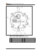
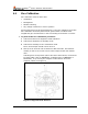
1 Remove the four (4) socket-head-screws (item 14, Figure 5) that secure
the Source back cover (item 15, Figure 5). The chamber is now open.
2 Remove the protective plug mounted on the source conduit/cable entry
inlet; pull the wires through the source inlet (item 4, Figure 7). Use a
3/4” – 14NPT or M25x1.5 explosion-proof conduit connection / cable
gland to assemble the cable / explosion-proof conduit to the source.
3 Connect the wires to the required terminals (item 2, Figure 7) (See
Terminal Wiring, page 39)
4 Connect the ground wire to the ground screw outside the source (item 3,
Figure 7). The source must be well grounded to earth ground.
5 Check wires for secure mechanical connection and press them neatly
against the terminal to prevent them from interfering while closing the
cover (item 15, Figure 5)
6 Place and secure the source back cover using four (4) socket-head-
screws (item 14, Figure 5)
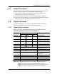
5.9.2 Terminal Wiring
The Flash Source contains a three-wire strip terminal:
Terminal 1 – positive (+) power supply
Terminal 2 – common return
Terminal 3 – GND (ground)