
Instruction Manual

SafEye
TM
Xenon 700S SIL Gas Detector
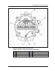
38 Detector Terminal Wiring
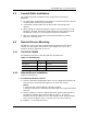
5.8 Detector Terminal Wiring
The Detector has three output wiring options in the rear, segregated, “Exde“
terminal section, with 9 Terminals, labeled 1-9.
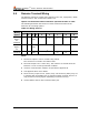
Option 3 is the default unless otherwise specified at time of order
The following describes the function of each electrical terminal of the
Detectors for all wiring options:
Table 18: Wiring Options
Wiring
Option
Terminal Number
1
2
3
4
5
6
7
8
9
3
Figure
11
(Default)
24Vdc
0Vdc
Alarm
Relay
(1)
RS-485+
(3)
RS-485-
(3)
0-20mA +
(4)
0-20mA -
(4)
RS-485
RTN
(6)
2
Figure
10
24Vdc
0Vdc
Alarm
Relay
(1)
Fault Relay
(2)
Accessory Relay
(5)
not used
1
Figure 9
24Vdc
0Vdc
Alarm
Relay
(1)
Fault Relay
(2)
0-20mA +
(4)
0-20mA -
(4)
not used
Notes:
1 The Alarm output is a N.O. contact relay (SPST).
The contacts are closed in Gas Alarm state.
2 The Fault output is N.C. SPST relay. The contacts are closed when the
Detector is in its normal operational condition.
3 Used for communication network as specified in Appendix B.
4 See Appendix B for more details
5 The Accessory output is N.O. (SPST) relay. The Accessory Relay may act
in parallel with the ALARM relay to activate another external device or it
may provide a warning signal, depending on Function Set Up.
6 Used as RTN to the RS-485 communication port.