
Instruction Manual

SafEye
TM
Xenon 700S SIL Gas Detector
34 Detector Wiring
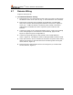
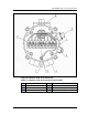
5.7 Detector Wiring
(Figure 5 and Figure 6)
➣ To install the Detector wiring:
1 Remove the four (4) socket-head-screws (item 14, Figure 5) that secure
the Detector back cover (item 15, fig. 4). The chamber is now revealed.
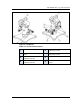
2 Remove the protective plug mounted on the Detector conduit/cable
entry inlet; pull the wires through the Detector inlet (item 4, Figure 6).
Use a 3/4” – 14NPT or M25x1.5 explosion-proof conduit connection /
cable gland to assemble the cable / explosion-proof conduit to the
Detector.
3 Connect the wires to the required terminals (item 2, Figure 6) according
to the wiring diagram. See Detector Terminal Wiring, page 38 and
Figure 9, Figure 10,Figure 11 Appendix B.
4 Connect the grounding wire to the ground screw outside Detector
(item 3. Figure 6). The Detector must be well grounded to Earth Ground.
5 Check the wires for secure mechanical connection and press them neatly
against the terminal to prevent them from interfering while closing the
cover (item 15, Figure 5)
6 Place and secure the Detector back cover using four (4) socket-head-
screws (item 14, Figure 5)