Xenon 700 SIL Open-Path Gas Detection System User's and Maintenance Manual ATEX, IECEx Approved Ex II 2(1) G, Ex d e ia [ia Ga] IIC T5 Gb Ta Document Ref: TM 799200, Rev. C January 2014 218 Little Falls Rd., Cedar Grove, NJ 07009 USA; Phone: +1 (973) 239 8398 Fax: +1 (973) 239 7614 Web-Site: www.spectrex.net; Email: spectrex@spectrex.
SafEyeTM Xenon 700S SIL Gas Detector ii
Legal Notice The SafEye monitoring system described in this document is the property of Spectrex, Inc. No part of the hardware, software or documentation may be reproduced, transmitted, transcribed, stored in a retrieval system, or translated into any language or computer language, in any form or by any means, without prior written permission of Spectrex, Inc. While great efforts have been made to assure the accuracy and clarity of this document, Spectrex, Inc.
SafEyeTM Xenon 700S SIL Gas Detector Release History Rev Date Revision History Prepared by Approved by A June 2011 First Release Ian Buchanan Eric Zinn B August 2013 Second Release Ian Buchanan Eric Zinn C January 2014 Third Release Ian Buchanan Eric Zinn iv Release History
About this Guide This guide describes the SafEyeTM Xenon 700S SIL Gas Detection System and its features and provides instructions on how to install, operate and maintain the detector. This guide includes the following chapters and appendixes: Chapter 1, Scope, provides a general introduction and overview of the product and the guide, with a brief description of its content. Chapter 2, Technical Description, describes the Detector’s theory of operation.
SafEyeTM Xenon 700S SIL Gas Detector Abbreviations and Acronyms vi Abbreviation Meaning ATEX Atmosphere Explosives AWG American Wire Gauge BIT Built In Test EMC Electromagnetic Compatibility EOL End of Line FOV Field of View HART Highway Addressable Remote Transducercommunication protocol IAD Immune at Any Distance IECEx International Electrotechnical Commission Explosion IPA Isopropyl Alcohol IR Infrared JP5 Jet Fuel Latching Refers to relays remaining in the ON state even aft
Table of Contents Xenon 700 SIL Open-Path Gas Detection System User's and Maintenance Manual ....................................................................... i Legal Notice .................................................................................................... iii Release History ............................................................................................... iv About this Guide..............................................................................................
SafEyeTM Xenon 700S SIL Gas Detector 3.1.4 3.2 Output Signals ......................................................................................17 3.2.1 Standard 0-20mA Current Output .....................................................17 3.2.2 Dry Contact Relays .........................................................................18 3.2.3 RS-485 Interface ............................................................................18 3.3 4 Zero Calibration Mode (1mA Output) ..............
TM 799200 Rev (C), January 2014 6 5.4 Certification Instructions ........................................................................32 5.5 Conduit/Cable Installation ......................................................................33 5.6 Detector/Source Mounting ......................................................................33 5.6.1 Tilt Kit P/N 799640..........................................................................33 5.6.2 Detector/Source Installation ..................
SafEyeTM Xenon 700S SIL Gas Detector C Special Conditions to Comply to SIL-2 Requirements .............................. 61 C.1 Safety relevant parameters (700S) .........................................................61 C.2 Guidelines for Configuration, Installation, Operation and Maintenance .........61 C.2.1 Conditions for Safe Operation ...........................................................61 C.2.2 Alarm Operation using the 0-20mA Signal Current ..............................62 C.2.
TM 799200 Rev (C), January 2014 List of Figures Figure 1: Wiring Options ....................................................................................10 Figure 2: Flash Source Unit ................................................................................11 Figure 3: Detector Unit ......................................................................................13 Figure 4: Tilt Mount ...........................................................................................
SafEyeTM Xenon 700S SIL Gas Detector List of Tables Table 1: Gas Concentrations Measurement Terms .................................................. 4 Table 2: Gas Calibrations .................................................................................... 6 Table 3: Model Numbers and Installation Distances ................................................ 9 Table 4: Detector Types .....................................................................................
1 Scope ➣ In this chapter… Product Overview 1.1 page 1 Product Overview The SafEye ‘Xenon’ IR Open-Path Gas Detector 700S employs an advanced Xenon Flash Source and integrated electronics package, both housed in improved, low-profile stainless steel housings to provide high quality and performance, fast response, line of sight gas monitoring. This high quality is backed by 3 years warranty for the complete SafEye system and 10 years for the Xenon Flash source bulb.
SafEyeTM Xenon 700S SIL Gas Detector 2 Product Overview
2 Technical Description ➣ In this chapter… 2.
SafEyeTM Xenon 700S SIL Gas Detector 2.2 Applications The SafEye Xenon system may be used to monitor flammable gas concentration in various applications, such as: 2.
TM 799200 Rev (C), January 2014 2.3.2 Spectral Finger Print Each hazardous material is detected at a specific wavelength selected according to its specific spectral absorption or "finger print". There are three IR sensors: two signals and one reference. The detection process involves two separate filters, one transmitting radiation that is absorbed by a particular gas and one that is not sensitive to it. 2.3.
SafEyeTM Xenon 700S SIL Gas Detector 2.3.6 Gas and Mixture Selection and Setting At the 3.4µ spectral band of the SafEye, the least sensitive gas is pure (100% vol) methane and the most sensitive gases are various mixtures of Methane with heavier alkanes where the Methane percentage is less than 90%. For pure Ethane the sensitivity is close to the high sensitivity gases and for pure Propane it lies somewhere between the two extremes.
TM 799200 Rev (C), January 2014 2.3.8 Heated Optics SafEye Xenon includes heated optics for the Detector and source. The heater increases the temperature of the optical surface by 5-8°F (3-5°C) above the ambient temperature to improve performance in icing, condensation and snow conditions. The heated optics is configured to automatically operate when the change in temperature requires the heating (default).
SafEyeTM Xenon 700S SIL Gas Detector 2.3.10 Handheld Unit The new I.S.-approved handheld diagnostics unit (Part no. 799810) is available to make installation and maintenance easier. This is an all-on-one diagnostic / calibration / interrogation plug-in unit that allows for oneperson installation and maintenance. The handheld unit can be used: For on-site function programming and set up changes to the Detector.
TM 799200 Rev (C), January 2014 2.5 Models and Types Series 700S offers 2 families of detected gases: Models 701S, 702S and 703S used for methane, LPG and gases mixture for most offshore and onshore applications. Models 721S, 722S and 723S used for ethylene only. Table 3 describes the installation distances for each of the Series 700S models. Table 3: Model Numbers and Installation Distances Model No. Detector Source Min. Installation Distance Max.
SafEyeTM Xenon 700S SIL Gas Detector Figure 1: Wiring Options 2.6 Description The SafEye is comprised of two main units: Flash Source Unit, page 11 Detector Unit, page 12 Xenon 700S detects gases over an open path transmitted from the Flash Source to the Detector.
TM 799200 Rev (C), January 2014 2.6.1 Flash Source Unit The Flash Source unit emits IR radiation pulses at the rate of two pulses per second. The pulse width (5-10msec) is very powerful. The front of the source SafEye has a coated lens that collimates the IR beam for maximum intensity. The coated lens blocks all the UV and visible lights from passing through the lens and prevents the flash pulse being visible to the eye. The lens is heated to improve performance in icing, condensation and snow conditions.
SafEyeTM Xenon 700S SIL Gas Detector 2.6.2 Detector Unit The Detector receives the transmitted pulsed radiation signals from the Flash Source. The signals are then amplified and fed into an analog to digital signal converter to be processed by the internal microprocessor. When the signals drop below a prescribed level, the internal microprocessor will compensate for them. This will allow the signal to be maintained even in severe weather conditions. The data is sent to the output interface section.
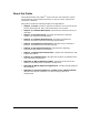
TM 799200 Rev (C), January 2014 1 Main Housing 6 Telescope Site 2 Junction Box 7 Handheld Fast Connection 3 Back Cover 8 Earth Terminal 4 Cable Inlet 9 Front Window/Window Section 5 Holding Plate Figure 3: Detector Unit Description 13
SafEyeTM Xenon 700S SIL Gas Detector 14 Description
3 Operational Modes ➣ In this chapter… 3.1 Operation Modes page 15 Output Signals page 17 System Set Up page 18 Operation Modes The SafEye 700S has four operational modes: 3.1.1 Normal Mode, page 15 Maintenance Call Mode (3mA Output), page 15 Fault Mode, page 16 Zero Calibration Mode (1mA Output), page 16 Normal Mode This mode is used for gas detection.
SafEyeTM Xenon 700S SIL Gas Detector 3.1.3 Fault Mode In the Fault status, there are three fault types: 3.1.4 Fault 1 (2mA Output) – Non critical: If this occurs, it is due to blockage, poor alignment, very low signal or in the case of partial obscuration or full beam block and detection is no longer possible. The Detector’s proper operation can be restored (Auto reset) during operation if the condition causing the problem is removed or resolved. This mode will occur after a delay of 60 sec.
TM 799200 Rev (C), January 2014 3.2 Output Signals The SafEye system provides the following outputs depending upon the wiring option selected (see Models and Types, page 9): 3.2.
SafEyeTM Xenon 700S SIL Gas Detector Table 6: Optional - Discrete Reading of 0-20mA at Different Detector Modes Current Reading LEL.m Setting 0+0.3mA Fault 2 or Low Voltage - 1±0.3mA Zero Calibration - 2±0.3mA Fault 1 - 3±0.3mA “Maintenance Call” - 4±0.5mA Standby - 14±0.5mA Warning 1 19±0.5mA Alarm 3 21mA 3.2.2 Status and Description Concentration is over the range limit (more than full-scale concentration).
TM 799200 Rev (C), January 2014 3.3.1 Detection Function Programming The SafEye 700S series incorporates several functions that can be set by the customer using: 3.3.2 Handheld unit (P/N 799810). Refer to manual TM 799060 for programming instructions. The connection of the handheld to the detector is fast and intrinsically safe and allows function change with no need to open the detector. To use the non I.S mini laptop Unit, refer to Manual TM 777070 for instructions.
SafEyeTM Xenon 700S SIL Gas Detector 3.3.2.3 Zero Calibration Zero Calibration can be enabled or disabled as follows: 3.3.2.4 Enable – Zero calibration is performed according to background Disable – The Detectors are not updated due to change of background Other Functions Table 8: Other Functions Function Accessory Relay Accessory Relay is activated at warning level Accessory Relay is activated at alarm level Alarm Latching No latching function at alarm relay Alarm relay is latched.
TM 799200 Rev (C), January 2014 The Source heated optic must be defined with the order in two options: 3.3.3 Heated continuously Start heating below 41°F (5°C). (default) Default Detector Set up The Detector has 8 functions that can be programmed according to the customer requirement at factory or at customer facility using a software Host or a handheld unit. The standard set up is as follows: Table 9: Detector Default Set Up * Function Setting Gas Type 2 Full scale sensitivity 5 LEL.
SafEyeTM Xenon 700S SIL Gas Detector 22 System Set Up
4 Technical Specifications ➣ In this chapter… 4.1 General Specifications page 23 Electrical Specifications page 24 Mechanical Specifications page 26 Environmental Specifications page 26 General Specifications Detected Gases: Simultaneous detection of C1-C8 flammable gases Detection Distance range: Table 11 Table 11: Detection Distance Range Model No. Detector Source Min. Installation Distance Max. Installation Distance 701S XDSS-C-111XX XSS-C-11X 13 ft. (4 m) 65 ft.
SafEyeTM Xenon 700S SIL Gas Detector 4.2 Electrical Specifications Operating Voltage: 4.2.1 18-32 VDC Power Consumption Table 12: Detector and Source Maximum Power Consumption Without Heated Optic (Max.) 4.2.2 With Heated Optic (Max.) Detector 220mA 300mA Source 220mA 300mA Electrical Input Protection The input circuit is protected against voltage-reversed polarity, voltage transients, surges and spikes according to MIL-STD-1275B. 4.2.
TM 799200 Rev (C), January 2014 4.2.4.3 It enables continuous communication between a single standard Modbus controller (Master device) and a serial Network of up to 247 Detectors. It enables connection between different types of Spectrex Detectors or other Modbus devices to the same Network. Relays Output The Detector may include up to three of the following relays depending on the wiring configuration selected.
SafEyeTM Xenon 700S SIL Gas Detector 4.3 Mechanical Specifications Enclosure: The Detector, Source and tilt mount are St. St. 316 Electro chemical and passivized coating.
TM 799200 Rev (C), January 2014 4.4.3 Humidity Designed to meet MIL-STD-810C, method 507.1, procedure IV relative humidity of up to 95% for the operational temperature range. 4.4.4 Salt and Fog Designed to meet MIL-STD-810C, method 509.1 procedure I. Exposure to a 5% salt solution for 48 hours. 4.4.5 4.4.6 4.4.7 Water and Dust IP67 per EN60529 IP66 per EN60529 Dust: Totally protected against dust Liquids: Protected against immersion between 15 cm and 1m in depth.
SafEyeTM Xenon 700S SIL Gas Detector 28 Environmental Specifications
5 Installation Instructions ➣ In this chapter… 5.1 Introduction page 29 General Considerations page 29 Preparations for Installation page 30 Certification Instructions page 32 Conduit/Cable Installation page 33 Detector/Source Mounting page 33 Detector Wiring page 34 Detector Terminal Wiring page 38 Flash Source Wiring page 39 Introduction The Detector and Flash Source units can be installed and maintained with the use of general-purpose common tools and equipment.
SafEyeTM Xenon 700S SIL Gas Detector 5.2.3 Site Requirements The installation position of the SafEye system must take into account if the gas being monitored is heavier or lighter than air, and the individual site requirements. The site selected must give the Detector a direct view to the Source. The mounting point for each item should be secure and stable with minimal vibrations. Equipment should be either mounted in a position where it cannot be knocked out of alignment, or guarded from physical impact.
TM 799200 Rev (C), January 2014 Two Tilt Mount Bases P/N 799640 1 base is used for the Detector 1 base is used for the Flash Source. The Commissioning kit includes Function Check Filter and the Telescope Kit, which is used during each SafEye installation and then removed. They can be reused for all other SafEye installations on the site. Therefore, only one set is provided for several detectors.
SafEyeTM Xenon 700S SIL Gas Detector 5.4 Certification Instructions Warning: Do not open the detector, even when isolated, when flammable atmosphere is present. Use the following certification instructions: The cable entry point may exceed 158°F (70°C) suitable precautions should be taken when selecting the cable. The equipment may be used with flammable gases and vapors with apparatus groups IIA, IIB and IIC T5 in the ambient temperature range -40°F (-40°C) to +131°F (+55°C).
TM 799200 Rev (C), January 2014 5.5 Conduit/Cable Installation The conduit and cable installation must comply with the following guidelines: 5.6 1 To avoid water condensation in the detector, install the Detector with the conduits/cable entries facing downwards 2 Use flexible conduits/cables for the last portion connecting to the detector 3 When pulling the cables through the conduits, ensure that they are not tangled or stressed.
SafEyeTM Xenon 700S SIL Gas Detector 5.7 Detector Wiring (Figure 5 and Figure 6) ➣ To install the Detector wiring: 34 1 Remove the four (4) socket-head-screws (item 14, Figure 5) that secure the Detector back cover (item 15, fig. 4). The chamber is now revealed. 2 Remove the protective plug mounted on the Detector conduit/cable entry inlet; pull the wires through the Detector inlet (item 4, Figure 6). Use a 3/4” – 14NPT or M25x1.
TM 799200 Rev (C), January 2014 Figure 4: Tilt Mount Table 15: Tilt Mount Description 1 Tilt Mount Holding Plate 5 Vertical Fine Alignment Tightening Screw Vertical Crude Alignment Tightening Screw 2 Detector/Source Holding Plate 6 3 Horizontal Crude Alignment Tightening Screw 7 4 Horizontal Fine Alignment Tightening Screw 8 Detector Wiring Vertical Fine Alignment Screw Horizontal Fine Alignment Screw 35
SafEyeTM Xenon 700S SIL Gas Detector Figure 5: Detector and Tilt Mount Assembly Table 16: Detector and Tilt Mount Assembly Description 36 1 Tilt Mount Holding Plate 9 2 Detector/Source Holding Plate 10 3 Horizontal Crude Alignment Tightening Screw 11 4 Horizontal Fine Alignment Tightening Screw 12 5 Vertical Fine Alignment Tightening Screw 13 6 Vertical Crude Alignment Tightening Screw 14 7 Vertical Fine Alignment Screw 15 8 Horizontal Fine Alignment Screw Detector Tightening Screw
TM 799200 Rev (C), January 2014 Figure 6: Detector with Cover Removed Table 17: Detector with Cover Removed Description 1 Housing 5 Internal Earth Connection 2 Terminal Board 6 Connection to Handheld Unit 3 Earth Terminal 7 Detector Holding Plate 4 Inlet Conduit 8 Detector Telescope Site Detector Wiring 37
SafEyeTM Xenon 700S SIL Gas Detector 5.8 Detector Terminal Wiring The Detector has three output wiring options in the rear, segregated, “Exde“ terminal section, with 9 Terminals, labeled 1-9.
TM 799200 Rev (C), January 2014 5.9 Flash Source Wiring 5.9.1 Wiring ➣ To install the wiring: 5.9.2 1 Remove the four (4) socket-head-screws (item 14, Figure 5) that secure the Source back cover (item 15, Figure 5). The chamber is now open. 2 Remove the protective plug mounted on the source conduit/cable entry inlet; pull the wires through the source inlet (item 4, Figure 7). Use a 3/4” – 14NPT or M25x1.
SafEyeTM Xenon 700S SIL Gas Detector Figure 7: Source with Cover Removed Table 19: Source with Cover Removed Description 40 1 Housing 5 Internal Earth Connection 2 Terminal Board 6 N/A 3 Earth Terminal 7 Detector Holding Plate 4 Inlet Conduit 8 Detector Telescope Site Flash Source Wiring
6 Operating Instructions ➣ In this chapter… 6.1 SafEye Operation page 41 Alignment of Unit page 41 Powering up the System page 42 Safety Precautions page 43 Signal Verification page 43 Zero Calibration page 44 Functional Check of Unit page 45 SafEye Operation After the system is positioned, it will monitor for possible specified gases automatically sending signals to a standard control panel or to a PC. This section describes the alignment, calibration and operation.
SafEyeTM Xenon 700S SIL Gas Detector 2 Install the Telescope Assembly (12) on the Telescope Site Mounting of the Source according to the drawing. Fasten the Telescope with Fastening Screw (13). 3 Crude Alignment: a. Use ¼” Allen screw driver for all alignment screws. b. Loosen screws 5, 6. c. Approximately aim the source horizontally toward the detector. d. Tighten screw 6. e. Loosen screws 3 and 4. f. Approximately aim the source vertically toward the detector. g. Tighten screw 3.
TM 799200 Rev (C), January 2014 6.4 Safety Precautions After powering up the system, the Detector requires minimal attention in order to function properly, but the following should be noted: 6.5 1 Follow the instructions in the Manual; refer to the drawings and specifications issued by the manufacturer. 2 Do not open the detector/source housing while power is supplied. 3 Disconnect external devices, such as automatic extinguishing systems before carrying out any maintenance task warranty.
SafEyeTM Xenon 700S SIL Gas Detector 6.6 Zero Calibration Zero calibration must be done after: Installation Realignment Window Cleaning Any change in Detector or Source position Precise alignment must be performed prior to the zero calibration procedure. Zero calibration should be performed in good weather conditions with insignificant gas concentrations in the surrounding environment or indoors.
TM 799200 Rev (C), January 2014 6.7 Functional Check of Unit The SafEye system has been calibrated at the factory for the User's specific gas or vapor detection requirements. The following procedure validates the functional operation of the system. The Functional Check Filter is a convenient operational check used to confirm that response has not changed from previous readings. The filter is not used for calibration, which is unnecessary, nor does it equate to a particular quantity of gas.
SafEyeTM Xenon 700S SIL Gas Detector 46 Functional Check of Unit
7 Maintenance Instructions ➣ In this chapter… 7.1 General Maintenance page 47 Periodic Maintenance page 47 General Maintenance The SafEye Xenon system requires only simple periodic maintenance to provide satisfactory service and achieve maximum performance. The Detector and Source units can be maintained with the use of common tools and equipment. Record the periodic test results in Maintenance Logbook with a copy of the delivery form inside. 7.
SafEyeTM Xenon 700S SIL Gas Detector 7.2.1 Routine Optical Surface Cleaning The SafEye system, being an optical device, must be kept as clean as possible. The optical surfaces concerned are the Source and Detector viewing windows. ➣ To clean the optical window, proceed as follows: 1 Turn off the power to the SafEye detector and source. 2 In places where dust or dirt has accumulated on the optical surface, clean the surface with a small, soft-bristle brush.
8 Troubleshooting ➣ In this chapter… Troubleshooting Problems 8.1 page 49 Troubleshooting Problems Table 21: Troubleshooting Problems Problem Cause Solution “Maintenance call” status or R, S1 and S2 are below 2.
SafEyeTM Xenon 700S SIL Gas Detector 50 Troubleshooting Problems
Appendices Appendices 51
SafEyeTM Xenon 700S SIL Gas Detector 52 Appendices
A Wire Selection Tables ➣ In this appendix… General Instructions For Electrical Wiring A.1 page 53 General Instructions For Electrical Wiring Refer to Table 22 to determine the required wire gauge for general wiring, such as relay wiring. Calculate the permitted voltage fall with respect to loads current, wire gauge and length of wires. Refer to Table 23 to select wire gauge for power supply wires. DO NOT connect any circuit or load to Detectors’ supply inputs.
SafEyeTM Xenon 700S SIL Gas Detector Table 23: Wiring length in feet (meter) No. of Detectors Recommended Wire Diameter Power Supply Range (VDC) 24 18 16 14 - - 22-32 20 18 16 14 - - 22-32 16 20 18 16 14 - 22-32 12 20 18 16 14 - 20-32 8 20 18 16 14 - 20-32 4 and less 20 18 16 16 14 20-32 Feet 164 328 492 656 820 (Meters) (50) (100) (150) (200) (250) Max.
B Wiring Option Configurations ➣ In this appendix… RS-485 Communication Network page 60 Figure 9: Wiring Option 1 Note: Only 0-20mA is SIL2 approved.
SafEyeTM Xenon 700S SIL Gas Detector Figure 10: Wiring Option 2 Note: This option does not comply with SIL2 requirements.
TM 799200 Rev (C), January 2014 Figure 11: Wiring Option 3 (Default) Note: Only 0-20mA is SIL2 approved.
SafEyeTM Xenon 700S SIL Gas Detector Figure 12: 0-20mA Wiring (Sink) For Wiring Option 1 and 3 Figure 13: 0-20mA Wiring (Source) For Wiring Option 1 and 3 Notes: 58 The Detectors are factory set to isolated 0-20mA-sink version. For non-isolated 0-20mA version (Source), connect Terminal 8 to Terminal 1. The 0-20mA meter is connected between Terminal 7 and Terminal 2.
TM 799200 Rev (C), January 2014 Figure 14: 0-20mA 3 Wire Connection for Option 1 and 3 Wiring Option Configurations 59
SafEyeTM Xenon 700S SIL Gas Detector B.1 RS-485 Communication Network By using the RS-485 network capability of the SafEye Xenon 700S Detector and additional software, it is possible to connect up to 32 Detectors in an addressable system with four (4) wires only (2 for power and 2 for communication). Using repeaters, the number of Detectors can be much larger (32 Detectors for each repeater) up to 247 on the same four (4) wires.
C Special Conditions to Comply to SIL-2 Requirements ➣ In this appendix… Safety relevant parameters (700S) page 61 Guidelines for Configuration, Installation, Operation and Maintenance page 61 Miscellaneous page 62 Special conditions to comply with the requirements of EN 61508 for SIL-2 This appendix details the special conditions to comply with the requirements of EN 61508 for SIL-2. The SafEye 700S can be used in low or high demand mode applications, see IEC 61508.4, Chapter 3.5.12. C.
SafEyeTM Xenon 700S SIL Gas Detector C.2.2 Alarm Operation using the 0-20mA Signal Current The connected controller has to monitor the 0-20mA signal current for valid values: (see cap. Output Signals) Mode Normal Warning Alarm Continuous current with low sensitivity (Full Scale: 5 LEL.m) 4 mA (0 LEL.m) 7.2 mA (1 LEL.m) 13.6 mA (3 LEL.m) Continuous current with high sensitivity (Full Scale: 2 LEL.m) 4 mA (0 LEL.m) 7.2 mA (0.4 LEL.m) 12 mA (1 LEL.
Technical Support For all technical assistance or support, contact: 218 Little Falls Road Cedar Grove, NJ 07009, USA Tel: +1 (973) 239 8398 Fax: +1 (973) 239 7614 Email: spectrex@spectrex.net Web-site: www.spectrex.net Your Local Office: SPECTREX INC. Texas (USA) Mr. Jay Cooley, Regional Sales Manager: 16203 Park Row, Suite 150 Houston, Texas 77084 USA Phone: +1 (832) 321 5229 Email: jay@spectrex.net Europe Mr.
SafEyeTM Xenon 700S SIL Gas Detector 64 Technical Support