
User guide


Spectrex Inc. - SafEye
TM
300 Gas Detector Manual – TM 794100, Rev. D, May 2004
65
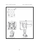
2.1 Terminal Wiring
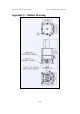
Each detector and source unit has a separate EExe terminal box directly
attached/assembled to it and prewired to the terminal strip in the EExe box (Item
4). There are two possible wiring options – please follow the wiring scheme
below which is appropriate to that ordered:
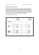
The terminal block is labeled 1 to 6 (See Fig. No.25)
The following describes the function of each electrical terminal of the detector:
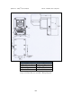
RS-485 & 4-20mA Version
Option A (See Fig. No. 26)
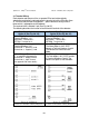
Alarm & Fault Relays Version
Option B (See Fig. No. 27)
Power Supply
(Terminal Numbers 1, 2):
Input power - Terminal No. 1.
RETURN - Terminal No. 2.
Power Supply
(Terminal Numbers 1, 2):
Input power - Terminal No. 1.
RETURN - Terminal No. 2.
RS-485 as specified in appendix C.
(Terminal Numbers 3, 4):
Terminal No. 3 - positive (+) lead.
Terminal No. 4 - negative (-) lead.
Alarm Relay (Terminal Numbers 3, 4):
The Alarm output is a NO. SPST
contact at Terminal Numbers 3 and 4.
The contacts are closed at Alarm
Mode.
4-20mA Output (Terminal Numbers 5,
6): as specified in paragraph 5.e
Terminal No. 5 - output Terminal.
Terminal No. 6 - input Terminal.
(see appendix B for more details)
Fault Relay (Terminal Numbers 5, 6):
The Fault output is N.C. SPST contact
at Terminal Numbers 5 and 6. The
contacts are open at Fault condition.
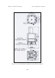
Figure 26: OPTION A
Detector Assembly - Wiring Diagram
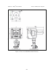
Figure 27: OPTION B
Detector Assembly - Wiring Diagram