
User guide

Spectrex Inc. - SafEye
TM
300 Gas Detector Manual – TM 794100, Rev. D, May 2004
10
Notes:
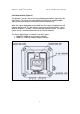
1 The number of flashes shows the intensity of the received signals while the
color represents the gain (see Table 3). The left LED shows the “tens” unit of
the number while the right LED displays the “one” unit of the number of the
signal intensity. Each LED will flash 0 to 9 times (9 being the maximum
possible signal intensity). When the left LED has reached its highest signal,
look at the right LED for fine adjustment.
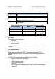
Table 3. Alignment Indication LED Color
Left LED Right LED Gain
Red Red 3
Orange Orange 2
Green Orange 1
Green Green 0
2 After 20 minutes at alignment mode the detector will return to normal mode.
3 After zero calibration is finished, the detector will return to normal mode and
the signal intensity will be saved for next alignment comparison.
4 The 4-20mA level in this Table refers to discrete indication option. A different
(continuous reading) option is described later in section 3.7.1
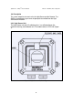
3.7 Output Signals
The SafEye system provides the following outputs:
• Standard 4-20mA port
• Three dry contact relays
• Optional RS-485 Output for PC Communications
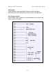
3.7.1 4-20mA Current Output
The 4-20mA output can provide the detector status measurement in one of the
two following methods:
1. It can be measured proportionally (default) showing a continuous reading
of the exact gas concentration (see Table 4).
2. It can be a discrete indication according to the detector mode or the
Warning or Alarm signal at a defined gas concentration. Setting of this
method can be done by SW3-2 selection (see Table 5).
The 4-20mA functions as current source. The maximum permitted load
resistance for the 4-20mA output is 600 ohms. The minimum permitted load
resistance is 100 ohms.