Series 300 Open-Path Gas Detection System User and Maintenance Manual TM 794100, Rev. D, June 2004 UL Approved E209870, Class I Group C and D ATEX (Cenelec) Approved Ex II 2 G, EExd IIB +H 2 T5 EExde IIB +H 2 T5 218 Little Falls Rd., Cedar Grove, NJ 07009 USA; Phone: +1 (973) 239 8398 Fax: +1 (973) 239 7614 Web -Site: www.spectrex-inc.com ; Email: spectrex@spectrex-inc.
The SafEye monitoring system described in this document is the property of Spectrex, Inc. No part of the hardware, software or documentation may be reproduced, transmitted, transcribed, stored in a retrieval system, or translated into any language or computer language, in any form or by any means, without prior written permission of Spectrex, Inc. While great efforts have been made to assure the accuracy and clarity of this document, Spectrex, Inc.
Spectrex Inc. - SafEyeTM 300 Gas Detector Manual – TM 794100, Rev. D, May 2004 TABLE OF CONTENTS 1. Scope ............................................................................................................................1 1.1 Product Overview................................................................................................... 1 1.2 Document Overview................................................................................................ 1 2. Technical Description............
Spectrex Inc. - SafEyeTM 300 Gas Detector Manual – TM 794100, Rev. D, May 2004 4.2 Electrical Specifications ........................................................................................ 20 4.3 Mechanical Specifications .................................................................................... 21 4.4 Environmental Specifications .............................................................................. 22 5. Installation Instructions ...............................................
Spectrex Inc. - SafEyeTM 300 Gas Detector Manual – TM 794100, Rev. D, May 2004 7. Maintenance Instructions...................................................................................... 49 7.1 General Maintenance............................................................................................ 49 7.2 Periodic Maintenance ........................................................................................... 49 7.2.1 Routine Optical Surface Cleaning ....................................
Spectrex Inc. - SafEyeTM 300 Gas Detector Manual – TM 794100, Rev. D, May 2004 LIST OF TABLES Table 1: Model Selection Guideline for SafEye Series 300 IR Type .................................. 5 Table 2. LED Status Indication........................................................................................... 9 Table 3. Alignment Indication LED Color........................................................................ 10 Table 4. Standard (default) 4-20mA Current for the Gas Channel ............
Spectrex Inc. - SafEyeTM 300 Gas Detector Manual – TM 794100, Rev. D, May 2004 1. Scope 1.1 Product Overview The SafEye 300 Series is an IR Open-Path Gas Detector that detects ambient combustible gases at LEL.m concentrations over a path length from 2ft (0.6m) up to 49 ft. (15 m), even in harsh environments where dust, fog, rain, snow or vibration can cause a high reduction of signal.
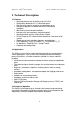
Spectrex Inc. - SafEyeTM 300 Gas Detector Manual – TM 794100, Rev. D, May 2004 2. Technical Description 2.1 Features • Operating distance from 2ft (0.
Spectrex Inc. - SafEyeTM 300 Gas Detector Manual – TM 794100, Rev. D, May 2004 2.3.1 Definitions of Terms The following list defines gas concentrations measurement terms that are used in this manual: LEL Lower Explosive Limit - The minimum concentration of a substance (gas/vapor) in air mixture that can be ignited. This mixture is different for every gas/vapor, measured in % of LEL. LEL.m Integral of Concentration in LEL units (1 LEL = 100% LEL) and the operation distance, or path length, in meters (m).
Spectrex Inc. - SafEyeTM 300 Gas Detector Manual – TM 794100, Rev. D, May 2004 2.3.5 Gas Sensitivity The SafEye IR Model uses wavelengths around 3.4µ spectral band to measure air flammability potential between the source and detector. At this wavelength, all hydrocarbon materials have a strong absorption peak. This peak enables the detector to achieve both regular sensitivity of 0-5 LEL.m or high sensitivity of 0-2 LEL.m according to functions set up.
Spectrex Inc. - SafEyeTM 300 Gas Detector Manual – TM 794100, Rev. D, May 2004 none of the four calibrations are appropriate, Spectrex, through local agents can advise how to calibrate a SafEye Detector to any specific gas. 2.4 Product Marking The SafEye 300 Series open path gas Detector and source unit are certified to: 1. ATEX Ex II 2 G per SIRA 00 ATEX 1161 & 1165 EExd IIB +H2 T5 and EExde IIB +H2 T5 Amb. Temp. -40°C to +70°C 2. UL E209870 Class I, Group C and D 2.
Spectrex Inc. - SafEyeTM 300 Gas Detector Manual – TM 794100, Rev. D, May 2004 2.6 Description The system comprises two main units; the Light Source and the Detector. The SafEye system detects gases over an open path transmitted from the Light Source to the Detector. 2.6.1 Light Source Unit The Light Source unit emits IR radiation pulses, in a collimated beam (for maximum intensity) to the detector unit. The model number is OPS-LI0x (Figure 1).
Spectrex Inc. - SafEyeTM 300 Gas Detector Manual – TM 794100, Rev. D, May 2004 2.6.2 Detector Unit (Figure 2) The detector's sensors receive the transmitted pulsed radiation signals from the Light Source. The signals are then amplified and fed into an analog to digital signal converter to be processed by the internal microprocessor. When the signals drop below a prescribed level, the internal microprocessor will compensate for them.
Spectrex Inc. - SafEyeTM 300 Gas Detector Manual – TM 794100, Rev. D, May 2004 3. Operation Mode The SafEye system has three operation modes; Normal, Alignment and Zero Calibration. 3.1 Normal Mode This mode is used for gas detection. The following status signals are possible: (see Table 2 for visual indications). Normal Warning Alarm - Signal received from gas detection is at safe levels. - Gases have been detected at warning levels. - Gases have been detected at alarm levels. 3.
Spectrex Inc. - SafEyeTM 300 Gas Detector Manual – TM 794100, Rev. D, May 2004 Zero calibration must be done after installation, re-alignment and window cleaning, using magnetic mode selection 3.5 Mode Selection A Magnetic Mode Selector is used to change to alignment and calibration modes by placing the magnet on the side of the detector (Figure 16). 3.6 Visual Indications LEDs There are two indicators (LEDs) located in the detector’s front window, referred to as the right and left LEDs.
Spectrex Inc. - SafEyeTM 300 Gas Detector Manual – TM 794100, Rev. D, May 2004 Notes: 1 The number of flashes shows the intensity of the received signals while the color represents the gain (see Table 3). The left LED shows the “tens” unit of the number while the right LED displays the “one” unit of the number of the signal intensity. Each LED will flash 0 to 9 times (9 being the maximum possible signal intensity).
Spectrex Inc. - SafEyeTM 300 Gas Detector Manual – TM 794100, Rev. D, May 2004 Table 4. Standard (default) 4-20mA Current for the Gas Channel Current Status and Description 0mA +0.5mA Fault 2 or Low Voltage 2mA ±0.5mA Fault 1 4mA ±0.5mA Zero reading - No gas detected 4-20mA Continuous measuring of gas concentration at a range between 0 and 5 LEL.m or full scale 21mA Concentration is over the range limit (more than full scale concentration). Table 5.
Spectrex Inc. - SafEyeTM 300 Gas Detector Manual – TM 794100, Rev. D, May 2004 3.8 Terminals Terminal outputs are described for the Detector and the Light Source. For EExde version with separate EExe terminal section, see Appendix D 3.8.1 Detector Terminal Terminal Wiring: Figure 3 displays a schematic diagram of the terminals and Figure 4 shows their location. Figure 3.
Spectrex Inc. - SafEyeTM 300 Gas Detector Manual – TM 794100, Rev. D, May 2004 1 2 3 4 5 Descrip tion Detector Cover Terminal Board Terminal Screw Securing Cable Conduits Figure 4.
Spectrex Inc. - SafEyeTM 300 Gas Detector Manual – TM 794100, Rev. D, May 2004 3.8.2 Light Source Terminals Figure 5 shows the terminal board and Table 6 describes their use. Figure 5. Light Source Terminal Board Table 6.
Spectrex Inc. - SafEyeTM 300 Gas Detector Manual – TM 794100, Rev. D, May 2004 3.9 System Setup 3.9.1 Detector Setting The detector consists of the following DIPswitches, which enable the user to adapt the detector operation to specific application: SW1 Function Selection Switch. Contains. 8 DIPswitches. Used for Calibration of different gas selection, response time control and Relays response configuration (see table 7) SW2 Address Selection Switch. Contains 8 DIPswitches.
Spectrex Inc. - SafEyeTM 300 Gas Detector Manual – TM 794100, Rev. D, May 2004 Notes: 1 Four Gas types can be selected for maximum compatibility to Gas spectral properties. The selection of the appropriate type is defined by pre-setting of SW1-3 and SW1-4 according to the following table: Table 8. Gas Type Calibration Setup bit # 0 position bit # 1 position Detected Gas (SW1-3) (SW1-4) Type off on off on off off on on Methane Mixture Propane Mixture Gas type as defined in Section 2.3.
Spectrex Inc. - SafEyeTM 300 Gas Detector Manual – TM 794100, Rev. D, May 2004 Table 9 describes SW2 DIPswitches position and the required function for setting the detector according to the necessary configuration Table 9. SW2 DIPswitches Configuration Switch Switch Definition Off On position No.
Spectrex Inc. - SafEyeTM 300 Gas Detector Manual – TM 794100, Rev. D, May 2004 Table 10 describes SW3 DIPswitches position and the required function for setting the detector according to the necessary configuration Table 10. SW3 DIPswitches Configuration Off position On position Switch No. 1 Non latching Alarm Relay 2 3 4 Continuous reading of the 4-20mA output reading Non-latching Alarm indications during Blocking Mode Normal Position (open) Alarm Relay latches.
Spectrex Inc. - SafEyeTM 300 Gas Detector Manual – TM 794100, Rev. D, May 2004 4. Technical Specifications 4.1 General Specifications Detected Gases: Simultaneous detection of C1-C8 flammable gases Detection Distance range: Table 11: Detection Distance Range Model No. 301 302 Distance (ft) 2-11.5 9.8-49 Distance (m) 0.6-3.5 3-15 Response Time 2 Sec. 10 Sec. Spectral Response: 3.0 - 4.0 micron Sensitivity Range: Table 12: Sensitivity Range 301 302 Standard 0-2.5 LEL.m 0-5 LEL.m DIPswitch 0-1 LEL.
Spectrex Inc. - SafEyeTM 300 Gas Detector Manual – TM 794100, Rev. D, May 2004 4.2 Electrical Specifications • • Operating Voltage: 18- 32 VDC Power Consumption Detector 150 mA @ 24 VDC (200 mA Peak) Source 100 mA @ 24 VDC (220 mA Peak) • Electrical input protection: The input circuit is protected against voltage-reversed polarity, voltage transients, surges and spikes according to MIL-STD-1275A. • Electrical Interface (see figure 4) • Electrical outputs A.
Spectrex Inc. - SafEyeTM 300 Gas Detector Manual – TM 794100, Rev. D, May 2004 4.3 Mechanical Specifications Enclosure: Explosion Proof: Electrical Modules: Electrical connection: Water and dust tight: Weight & Dimensions The source and detector housings are made of either anodized aluminum with less than 1% Mg with an epoxy enamel finish, or St.St. 316L enclosure with electro polish finish The back covers are all sealed with special "O" rings to prevent intrusions such as dust, salt and sprays.
Spectrex Inc. - SafEyeTM 300 Gas Detector Manual – TM 794100, Rev. D, May 2004 4.4 Environmental Specifications The SafEye system is designed to withstand harsh environmental conditions. The Source and Detector units compensate for adverse conditions while maintaining accuracy. • High Temperature: Designed to meet MIL-STD-810C, method 501.1 procedure II Operating temperature: +158 ºF (+70 º C) Storage temperature: +158 ºF (+70 º C) • Low Temperature: Designed to meet MIL-STD-810C, method 502.
Spectrex Inc. - SafEyeTM 300 Gas Detector Manual – TM 794100, Rev. D, May 2004 5. Installation Instructions The Detector and Light Source units can be installed and maintained with the use of general-purpose common tools and equipment. The installation procedure has to be performed by suitably qualified personnel. 5.1 Introduction This section does not attempt to cover all of the standard practices and codes of installation.
Spectrex Inc. - SafEyeTM 300 Gas Detector Manual – TM 794100, Rev. D, May 2004 The open path between the Source and Detector and the immediate surroundings should be kept clear of obscuration that might hinder the free movement of air in the protected area or block the infrared beam. 5.2.5 Guidance Tips for Gas Detector Locations Guidance Tips for Gas Detector locations in order to provide the best detection coverage: 1. Below potential leak source for heavier than air gases 2.
Spectrex Inc. - SafEyeTM 300 Gas Detector Manual – TM 794100, Rev. D, May 2004 5.4 Mounting for Standard Open-Path Installation The following instructions are applicable for both the Light Source unit and the Detector unit. The detector may be mounted on special Swivel Mounts (see 5.4.1) or i. Tilt Mounts (see 5.4.3) ii. Duct mounts – (see5.5) iii. Also see appendix D if EExde version used 5.4.1 Swivel Mount Kit Note For Aluminum and St. St.
Spectrex Inc. - SafEyeTM 300 Gas Detector Manual – TM 794100, Rev. D, May 2004 Description Detector / Light Source Assembly 2 Swivel Mount Securing Plate 3 Protective Front Cover 4 Swivel Mount Alignment Plate 5 Swivel Mount Locking Screws 6 Vertical Adjustment Screws 7 Horizontal Adjustment Screws 8 Detector Screws 9 Swivel Mount Plate Securing Screws 10 Swivel Mount Holding Plate 1 Figure 6.
Spectrex Inc. - SafEyeTM 300 Gas Detector Manual – TM 794100, Rev. D, May 2004 5.4.3 Tilt Mount Kit The Tilt Mount kit includes the items listed in Table 16 as follows: Table 16. Tilt Mount Kit Qty DWG Tilt Mount 1 799220 Cap Socket 1 Screw 5/16 - 18 UNC - 2H 3/4” St.St. Spring Washer 1 Spring Washer 5/16” St.St. Detector Base Assembly 1 799110 Cap Socket Screw 4 Screw 1/4” - 20 UNC - 3A x 1/22 Spring Washer 4 1/4” St.
Spectrex Inc. - SafEyeTM 300 Gas Detector 1 Tilt Mount Holding Plate 2 Detector base Manual – TM 794100, Rev. D, May 2004 Description 7 8 3 Horizontal crude alignment tighten screw 4 Horizontal fine alignment tighten screw 5 Vertical fine alignment tighten screw 6 Vertical crude alignment tighten screw 9 Vertical fine alignment screw Horizontal fine alignment tighten screw Telescope 10 11 Telescope tightening bolt Detector / Source Figure 8.
Spectrex Inc. - SafEyeTM 300 Gas Detector Manual – TM 794100, Rev. D, May 2004 5.4.4 Detector / Source Installation (Figure No. 7 and 8) 1. Place the Tilt Mount holding plate (Item 1) in its designated location and secure it with (4) fasteners through four (4) holes dia. 8.5mm. 2. Install the Detector Base Assy. (Item 2) on the Tilt Mount use cap socket screw (Item 3) and Spring Washer (Item 4). Notes: 1 Skip steps 1 and 2 if the Tilt Mount is already installed.
Spectrex Inc. - SafEyeTM 300 Gas Detector Manual – TM 794100, Rev. D, May 2004 5.5.2 Duct Alignment Set (Figure 12) and Accessories Air Duct Installation has a limitation, which is the disability of viewing the Detector’s front and performing fine alignment through detector aiming such as performed in standard installation. As a result, fine alignment of the Detector’s Mount should be performed before the detector assembly is mounted to it.
Spectrex Inc. - SafEyeTM 300 Gas Detector 1 2 3 Manual – TM 794100, Rev. D, May 2004 Description Air Duct Installation Surface Duct Mount Screw Securing Hole Hole for Detector / Light Source Figure 9.
Spectrex Inc. - SafEyeTM 300 Gas Detector Manual – TM 794100, Rev. D, May 2004 5.5.4.Duct Mount Installation (Figures 10,11) The following instructions are applicable for both the Light Source unit and the Detector unit. 1. Insert the first Internal Plate (1) through the Air Duct Hole. Hold it by hand and press the Base Plate Gasket (2) to the Installation Surface against the Internal Plate. The Internal Plate Screws should be inserted into the Gasket holes and hold it from falling.
Spectrex Inc. - SafEyeTM 300 Gas Detector 1 Internal Plate 2 Base Plate Gasket 3 Base Plate 4 7 Base Plate Securing Nut and Flat Washer Window Plate Window Plate Nut and Flat Washer Window 8 Alignment Plate 5 6 Manual – TM 794100, Rev.
Spectrex Inc. - SafEyeTM 300 Gas Detector 1 2 3 4 5 6 7 8 Manual – TM 794100, Rev.
Spectrex Inc. - SafEyeTM 300 Gas Detector Manual – TM 794100, Rev. D, May 2004 5.5.5 Duct Mount Alignment (Figures 11,12) The following instructions are applicable for both the Light Source unit and the Detector unit. 1. Connect the Telescope Plate (Figure 12, item 1) to the Duct Mount Alignment Plate (Figure 11, item 8). Insert each one of four Screws (Figure 11, item 15) from the Duct Mount side through the Hole (Figure 12, item 2), and secure it with Nut and Flat Washer (Figure 11, item 15). 2.
Spectrex Inc. - SafEyeTM 300 Gas Detector 1 2 3 Manual – TM 794100, Rev. D, May 2004 Description Telescope Plate Detector / Light Source Securing Screw Hole Telescope Aim Figure 12.
Spectrex Inc. - SafEyeTM 300 Gas Detector Manual – TM 794100, Rev. D, May 2004 5.6 Detector Wiring (see appendix D if EExde version used) This section does not attempt to cover all of the standard practices and codes of installation. It emphasizes specific points providing the basic concept for qualified wiring installation personnel. Warning! Do not separate or close the housing section from the cover while the power is at “on” position.
Spectrex Inc. - SafEyeTM 300 Gas Detector Manual – TM 794100, Rev. D, May 2004 5.6.2 Harness Connection (Figure 13) 1. Remove the four Threaded Plugs (13) from detector front. 2. Release the four Socket-Head Screws (14) that secure the detector housing (1) to its back cover (2) using No. 5 Hex Key for M6 screw. Hold the housing during the removal of the screws. Pull the detector housing from its cover. The cover remains attached to the detector swivel mount.
Spectrex Inc. - SafEyeTM 300 Gas Detector 1 2 3 4 5 6 7 8 Housing Cover Screw Hole Female D Connector Male D Connector Conduit Inlet Plug Ground Terminal Screw Securing Cable Manual – TM 794100, Rev. D, May 2004 Description 9 SW1 10 SW3 11 SW2 12 Terminal Board 13 Threaded Plug 14 Socket Head Screw (M6x1.0Px50) 15 Screw Pan Head (No. 4-40UNC-2Ax3/8”) 16 Cable Tie Figure 13.
Spectrex Inc. - SafEyeTM 300 Gas Detector Manual – TM 794100, Rev. D, May 2004 5.6.3 Detector Terminal Wiring The detector contains a terminal board consisting of two terminal blocks. Power Supply: The input power is supplied to terminal 1. The Return is connected to 2. Note Ensure that the detector unit receives a minimum of 18 Volts DC and does not exceed 32 Volts DC. Fault Relay: The Fault Relay is normally open. The SPST relay is at terminal 4 and 5.
Spectrex Inc. - SafEyeTM 300 Gas Detector Manual – TM 794100, Rev. D, May 2004 5.7 Light Source Wiring 5.7.1 Power Supply Input power is supplied to terminal 1. The return is connected to terminal 2 (see figure 14). Note Ensure that the Light Source unit will receive a minimum of 18 Volts DC and does not exceed 32 Volts DC. Pre-wiring requirements and wiring requirements are identical to the appropriate requirements for the detector, as described in appendix A. 5.7.
Spectrex Inc. - SafEyeTM 300 Gas Detector 1 2 3 4 Housing Cover Conduit /cable Inlet Plugs Ground Terminal Screw Manual – TM 794100, Rev. D, May 2004 Description 5 Grounding Wire 6 Securing Cable 7 Screw Hole 8 DIPswitches Figure 14.
Spectrex Inc. - SafEyeTM 300 Gas Detector Manual – TM 794100, Rev. D, May 2004 6. Operating Instructions 6.1 SafEye Operation Once the system is positioned, it will monitor for possible specified gases, automatically sending signals to a standard control panel or a PC. This chapter describes the alignment, calibration and operation. Important! Accurate Alignment is essential for proper operation of the SafEye system. 6.2 Alignment of Unit (Figures 15 through 16) Using Swivel Mount (See 6.
Spectrex Inc. - SafEyeTM 300 Gas Detector 1 2 3 4 Manual – TM 794100, Rev. D, May 2004 Description Magnetic Mode Selector 5 Horizontal Adjustment Screw Detector Housing 6 Sight Cover Screw Detector Cover 7 Protective Sight Cover Vertical Adjustment Screw 8 Adjustment Screw Securing Nut Figure 15.
Spectrex Inc. - SafEyeTM 300 Gas Detector Manual – TM 794100, Rev. D, May 2004 4. Detector Crude Alignment: Refer to Figure 16 for all the following instructions. a. Use 3/16” Allen screwdriver to loosen up the 3 socket set screws (7). b. Tilt the Light Source in the general direction of the Detector. c. Rotate the Periscope (4) until its ocular is positioned in front of your aiming eye for most convenient observation. d.
Spectrex Inc. - SafEyeTM 300 Gas Detector Manual – TM 794100, Rev. D, May 2004 6.3 Alignment of Unit (Figure 7, 8) Using Tilt Mount Using the Telescope performs full alignment. Alignment procedure should be performed in two stages: Crude alignment then fine adjustment. The Telescope includes a Periscope that consists of a prism and an ocular located vertical to the Telescope assembly.
Spectrex Inc. - SafEyeTM 300 Gas Detector Manual – TM 794100, Rev. D, May 2004 6.4 Powering on the system Important! Prior to any operation or maintenance follow the Safety Precautions given at section 6.5 1. 2. 3. 4. Make sure that the source and detector are connected to the power. Make sure that the 4-20mA meter is connected to the detector. Power up the system 18-32VDC. After 60 seconds, the left LED lights at green, the current meter will indicate 4mA.
Spectrex Inc. - SafEyeTM 300 Gas Detector Manual – TM 794100, Rev. D, May 2004 2. Switch from Alignment to Standby mode. The LEDs will flash alternately with a green color. 3. Switch from Standby to Calibration mode. The LEDs will turn off. 4. Wait up to 60 seconds until it switches to Normal mode (right LED green) The detector reading is now set to normal. The 4-20mA output should indicate 4mA. 6.
Spectrex Inc. - SafEyeTM 300 Gas Detector Manual – TM 794100, Rev. D, May 2004 7. Maintenance Instructions 7.1 General Maintenance The SafEye system requires only simple periodic maintenance to provide satisfactory service and achieve maximum performance. The Detector and Source units can be maintained with the use of common tools and equipment. Record the periodic test results in a Maintenance Logbook with a copy of the delivery form inside.
Spectrex Inc. - SafEyeTM 300 Gas Detector Manual – TM 794100, Rev. D, May 2004 7.2.1 Routine Optical Surface Cleaning The SafEye system, being an optical device, must be kept as clean as possible. The optical surfaces concerned are the Source and Detector viewing windows. To clean the optical window, proceed as follows: 1. Turn off the power to the SafEye detector and source. 2. Where dust or dirt has accumulated on the optical surface, clean the surface with a small, soft-bristle brush. 3.
Spectrex Inc. - SafEyeTM 300 Gas Detector Manual – TM 794100, Rev. D, May 2004 Example: At a hypothetical installation the LEDs are Green-Orange with 3 green flashes (left LED) and 6 orange flashes (right LED). The number is 36 + 124 = 160 The next periodic maintenance reading has Orange-Orange LEDs with 8 orange blinks (left LED) and 8 orange flashes (right LED). The number is 88 + 62 = 150 The variance is 160-150 = 10 Units The percentage of variance will be (10/160)*100 = 6.
Spectrex Inc. - SafEyeTM 300 Gas Detector Manual – TM 794100, Rev. D, May 2004 8. Troubleshooting Problem LEDs are off and Fault is indicated at 0 mA level Both LEDs are on at yellow and fault is indicated at 0mA level Both LEDs are flashing at yellow and fault is indicated at 0mA level One LED is on at yellow and 4-20mA indication level is 2mA Cause Power is not supplied to the Detector Fault 2 Solution Supply power to the Detector Bring the detector unit for service.
Spectrex Inc. - SafEyeTM 300 Gas Detector Manual – TM 794100, Rev. D, May 2004 Appendix A - Wire Selection Tables General Instructions For Electrical Wiring 1. mA output or relay wiring - refer to Table 20 to determine the required wire gauge for general wiring Calculate the permitted voltage fall with respect to loads current, wire gauge and length of wires. 2. Power supply wires - refer to Table 21 to select wire gauge. DO NOT connect any circuit or load to Detectors’ supply inputs. Table 19.
Spectrex Inc. - SafEyeTM 300 Gas Detector Manual – TM 794100, Rev.
Spectrex Inc. - SafEyeTM 300 Gas Detector Manual – TM 794100, Rev. D, May 2004 Appendix B: Wiring Option configurations Figure 17.
Spectrex Inc. - SafEyeTM 300 Gas Detector Manual – TM 794100, Rev. D, May 2004 Figure 18. 4-20mA Source Output Figure 19.
Spectrex Inc. - SafEyeTM 300 Gas Detector Manual – TM 794100, Rev. D, May 2004 RS-485 Communication Network By using the RS-485 network capability of the SafEye Detector and additional software, it is possible to connect up to 32 Detectors in an addressable system with four (4) wires only (2 for power and 2 for communication). Using repeaters, the number of Detectors can be much larger (32 Detectors for each repeater) up to 64 on the same four (4) wires.
Spectrex Inc. - SafEyeTM 300 Gas Detector Manual – TM 794100, Rev.
Spectrex Inc. - SafEyeTM 300 Gas Detector Manual – TM 794100, Rev. D, May 2004 Appendix C: Outline Drawing Figure 21.
Spectrex Inc. - SafEyeTM 300 Gas Detector Manual – TM 794100, Rev. D, May 2004 Figure 22.
Spectrex Inc. - SafEyeTM 300 Gas Detector Manual – TM 794100, Rev. D, May 2004 Figure 23.
Spectrex Inc. - SafEyeTM 300 Gas Detector Manual – TM 794100, Rev. D, May 2004 Figure 24.
Spectrex Inc. - SafEyeTM 300 Gas Detector Manual – TM 794100, Rev. D, May 2004 Appendix D - Mounting the “EExde approved” version The EExde approved version provides an additional EExe terminal box attached below the EExd detector and therefore allows easier access in hazardous areas (see fig. 25). The unit is prewired to the terminals in the additional EExe terminal section ready for field wiring connections 1. Detector/Source Mounting The detector should be mounted by one of the following options: a.
Spectrex Inc. - SafEyeTM 300 Gas Detector Manual – TM 794100, Rev. D, May 2004 Description 1. Modified Back Cover 2. EExe Chamber Cover 3. Slotted Screw 4. Terminal Block 5. Ground Terminal 6. Mounting Thread 7. EExe Chamber 8.
Spectrex Inc. - SafEyeTM 300 Gas Detector Manual – TM 794100, Rev. D, May 2004 2.1 Terminal Wiring Each detector and source unit has a separate EExe terminal box directly attached/assembled to it and prewired to the terminal strip in the EExe box (Item 4). There are two possible wiring options – please follow the wiring scheme below which is appropriate to that ordered: The terminal block is labeled 1 to 6 (See Fig. No.
Spectrex Inc. - SafEyeTM 300 Gas Detector Manual – TM 794100, Rev. D, May 2004 For additional details or assistance, please contact 218 Little Falls Road Cedar Grove, NJ 07009, USA Tel: +1 (973) 239-8398 Fax: +1 (973) 239-7614 Email: spectrex@spectrex-inc.com Web-site: www.spectrex-inc.