
Manual


Spectrex Inc. - SafEye
TM
200 Gas Detector Manual – TM 792100, Rev. D, May 2004
55
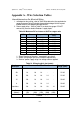
Appendix A - Wire Selection Tables
General Instructions For Electrical Wiring
1. mA output or relay wiring - refer to Table 20 to determine the required wire
gauge for general wiring Calculate the permitted voltage fall with respect
to loads current, wire gauge and length of wires.
2. Power supply wires - refer to Table 21 to select wire gauge. DO NOT
connect any circuit or load to Detectors’ supply inputs.
Table 20. Maximum DC resistance at 68°F for copper wire
AWG # mm
2
Ohm per 100 ft. Ohm/100
meter
26 0.12 - 0.15 4.32 14.15
24 0.16 - 0.24 3.42 11.22
22 0.30 - 0.38 1.71 5.60
20 0.51 - 0.61 1.07 3.50
18 0.81 - 0.96 0.67 2.20
16 1.22 - 1.43 0.43 1.40
14 1.94 - 2.28 0.27 0.88
12 3.09 - 3.40 0.17 0.55
10 4.56 - 6.64 0.11 0.35
1. Select "Number of Detectors" connected in one circuit.
2. Select "wiring length" per your installation requirements.
3. Refer to "power supply range" for voltage extreme applied.
Table 21. Wiring length in feet (meter)
No. of
Detectors
Recommended Wire Diameter Power Supply
Range (VDC)
24 18 16 14 - - 22-32
20 18 16 14 - - 22-32
16 20 18 16 14 - 22-32
12 20 18 16 14 - 20-32
8 20 18 16 14 - 20-32
4 and less 20 18 16 16 14 20-32
Feet 164 328 492 656 820
(Meters) (50) (100) (150) (200) (250)
Max. Length from Power Supply to Last
Detector