
Manual

Spectrex Inc. - SafEye
TM
200 Gas Detector Manual – TM 792100, Rev. D, May 2004
16
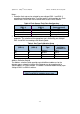
3.9 System Setup
3.9.1 Detector Setting
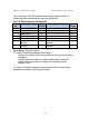
The detector consists of the following DIPswitches, which enable the user to
adapt the detector operation to specific application:
SW1 Function Selection Switch. Contains. 8 DIPswitches. Used for Calibration
of different gas selection, response time control and Relays response
configuration (see table 7)
SW2 Address Selection Switch. Contains 8 DIPswitches. Used for Detector’s
address setting and 4-20mA output configuration setting (see table 10)
SW3 Alarm Options Selection Switch. Contains 4 DIPswitches. Used for
Detector’s Alarm Latching configuration and 4-20mA level reading
configuration (see table 11)
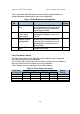
Function Selection Switch:
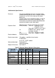
Table 7 describes SW1 DIPswitches position and the required function for setting
the detector according to the necessary configuration
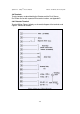
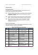
Table 7. SW1 DIPswitches Configuration
Switch
No.
Off position On position Default
setting
1 Detection speed control bit
0 at “0” (see note 1 below)
Detection speed control bit 0
at “1” (see note 1 below)
on
2 Detection speed control bit
1 at “0” (see note 1 below)
Detection speed control bit 1
at “1” (see note 1 below)
off
3 Gas type control bit 0 at “0”
(see note 2 below)
Gas type control bit 0 at “1”
(see note 2 below)
on
4 Gas type control bit 1 at “0”
(see note 2 below)
Gas type control bit 1 at “1”
(see note 2 below)
off
5 Full scale sensitivity is 0-5
LEL.m
Full scale sensitivity is 0-2
LEL.m
off
6 Zero calibration is
performed according to
background
Gas level detection
performed without
background Zero calibration
off
7 Accessory Relay is
activated at Warning level
Accessory Relay is activated
at Alarm level (with the
Alarm Relay)
off
8 Accessory Relay is
activated according to SW1-
7 position
Accessory Relay is Activated
at Power on continuously
(used as End of Line)
off