
Instruction Manual


Spectrex Inc. - SharpEye
TM
IR3 Flame Detector Manual – TM 20/20I, Rev. (6) August 2004
10
4.2 Output Signals
The detector controls the following outputs:
•
Alarm relay
• Accessory relay
• Fault relay
•
4-20mA current output
•
RS-485 communication
The detector can be in one of the following states.
Normal: The detector is functioning normally.
BIT: The detector performs a Built-In-Test.
Warning: Fire detected - changed to warning – pre-alarm state.
Alarm: Fire detected - changed to fire alarm state.
Latched Alarm
(Optional)
The alarm outputs are latched due to the detection of a fire that
has already been extinguished.
Fault: A fault is detected during a BIT sequence or the power supply is
too low. In each state the detector will activate different outputs
as specified in table 5.
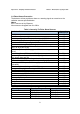
Table 5: Output Signals Versus Detector State
Detector
State
SW1 Power
Led
Alarm
Led
Alarm
Relay
Accessory
Relay
Fault
Relay
4-20mA
Output
Normal
On Off Off Off On 5mA
Warning Sw1-2 ON On Blink
2Hz
Off On On 10mA
Alarm On On On On On 15mA
Latch Sw1-1 ON On Off On Off On 5mA
Fault Blink
4Hz
Off Off Off Off 0mA
• The detector will be in its FAULT state until it has passed a successful BIT.
•
When SW1-2 is OFF, WARNING state is the same as the ALARM state.
• The alarm outputs will be activated as long as the alarm conditions are present
and will stop approximately 5 seconds after the fire is no longer detected.