
User guide

Spectrex Inc. - SharpEye
TM
Hydrogen (SH) Flame Detector Manual – TM 784600, Rev. A, May 2005
9
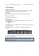
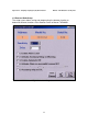
4.2 Output Signals
The detector controls the following outputs:
• Alarm relay
• Accessory relay
•
Fault relay
•
4-20mA current output
• RS-485 communication
The detector can be in one of the following states.
Normal: The detector is functioning normally.
BIT: The detector performs a Built-In-Test.
Warning: Fire detected - changed to warning – pre-alarm state.
Alarm: Fire detected - changed to fire alarm state.
Latched Alarm
(Optional)
The alarm outputs are latched due to the detection of a fire that
has already been extinguished.
BIT Fault: A fault is detected during BIT sequence. The detector will
continue to detect fire if the alarm conditions occur.
Fault: A fault is detected when the power supply is too low or during a
software fault.
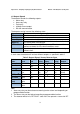
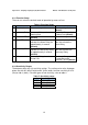
In each state the detector will activate different outputs as specified in table 5.
Table 5: Output Signals Versus Detector State
Detector
State
Power
Led
Alarm
Led
Alarm
Relay
Accessory
Relay
Fault
Relay
4-20mA
Output
Normal On Off Off Off On 5mA
Warning On Flash
2Hz
Off On
(1)
On 10mA
Alarm
(4)
On On On On On 15mA
Latch
(2)
On On On Off On 15mA
On On On On
(1)
On 15mA
BIT Fault
(3)
Flash Off Off Off Off 2mA
Warning at
BIT Fault
Flash
4Hz
Flash
4Hz
Off On
(1)
Off 10mA
Alarm at BIT
Fault
Flash
4Hz
On On On Off 15mA
Fault Flash
4Hz
Off Off Off Off 0mA
Note:
1 Accessory relay can be activated at warning level or alarm level depending on
programmable function
2 The Alarm state can be latched according to programmable function
3 The detector will be in its BIT FAULT state until it has passed a successful BIT.