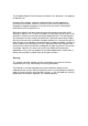
Mini Flame Detectors UV/IR - Model 20/20ML & UV - Model 20/20MU User and Maintenance Manual TM 767100, Rev. A, April 2005 20/20MU (Plastic Housing) 20/20ML (St.St Houdsing) 218 Little Falls Rd., Cedar Grove, NJ 07009 USA; Phone: +1 (973) 239 8398 Fax: +1 (973) 239 7614 Web-Site: www.spectrex.net; Email: spectrex@spectrex.
The SharpEye Optical Flame Detector described in this document is the property of Spectrex, Inc. No part of the hardware, software or documentation may be reproduced, transmitted, transcribed, stored in a retrieval system, or translated into any language or computer language, in any form or by any means, without prior written permission of Spectrex, Inc. While great efforts have been made to assure the accuracy and clarity of this document, Spectrex, Inc.
Spectrex Inc. - SharpEyeTM ML & MU Flame Detector Manual – TM 767100, Rev. A, April 2005 TABLE OF CONTENTS 1. Scope ..................................................................................................... 1 1.1 PRODUCT OVERVIEW .....................................................................................1 1.2 DOCUMENT OVERVIEW ...................................................................................1 2. Technical Description ................................................
Spectrex Inc. - SharpEyeTM ML & MU Flame Detector Manual – TM 767100, Rev. A, April 2005 7.4 FUNCTIONAL TESTING ...................................................................................29 7.4.1 Manual BIT Test .................................................................................30 7.4.2 Testing with Fire Simulator Model 20/20-311 (see Appendix B) ........30 7.5 SAFETY PRECAUTIONS .................................................................................31 8.
Spectrex Inc. - SharpEyeTM ML & MU Flame Detector Manual – TM 767100, Rev. A, April 2005 LIST OF FIGURES Figure 1: UV/IR Flame Detector........................................................................................ 5 Figure 2: UV Flame Detector............................................................................................. 5 Figure 3: Flame Detector Assembly - Outline Drawing - Cable output option ................
Spectrex Inc. - SharpEyeTM ML & MU Flame Detector Manual – TM 767100, Rev.
Spectrex Inc. - SharpEyeTM ML & MU Flame Detector Manual – TM 767100, Rev. A, April 2005 1. Scope 1.1 Product Overview The Spectrex Model 20/20ML UV/IR and 20/20MU UV Flame Detectors are designed to sense the occurrence of fire and flames and subsequently activate an alarm or an extinguishing system, directly or through a control circuit for maximum fire protection. They use the innovative technology of advanced digital signal processing to analyze the dynamic characteristics of fire.
Spectrex Inc. - SharpEyeTM ML & MU Flame Detector Manual – TM 767100, Rev. A, April 2005 2. Technical Description • • • • • • Detection Range: up to 50 ft (15m) for a 1 ft2 (0.1m2) fire. Two Response Levels: Warning & Detection. Solar Blind Microprocessor Based: Digital signal processing. Built In Test (BIT): Manual and Automatic (see section. 4.4). Electrical Interface: o Dry contact relays o Communication network RS-485 o 4-20mA output 2.
Spectrex Inc. - SharpEyeTM ML & MU Flame Detector Manual – TM 767100, Rev. A, April 2005 2.2 Sensing Elements 20/20ML The IR sensor is sensitive to radiation over the range of 2.5-3.0 micron. The IR channel will register a detection signal, at the appropriate level, when the IR sensor is exposed to radiation in the appropriate frequency range, having an intermittent gleam pattern characteristic to flickering-fire, and when a preset threshold and time duration are reached.
Spectrex Inc. - SharpEyeTM ML & MU Flame Detector Manual – TM 767100, Rev. A, April 2005 2.4 Types and Models The 20/20ML and 20/20MU have two (2) housing options: St. St. 316L, and plastic. The output is via either a connector (socket) or a cable tail (up to 2m long).
Spectrex Inc. - SharpEyeTM ML & MU Flame Detector Manual – TM 767100, Rev.
Spectrex Inc. - SharpEyeTM ML & MU Flame Detector Manual – TM 767100, Rev.
Spectrex Inc. - SharpEyeTM ML & MU Flame Detector Manual – TM 767100, Rev.
Spectrex Inc. - SharpEyeTM ML & MU Flame Detector Manual – TM 767100, Rev. A, April 2005 3. Performance 3.1 Detection Sensitivity Detection sensitivity is the maximum distance at which the detector will reliably detect a specific size of fire & typical type of fuel (standard fire). Standard Fire: A 1ft2 (0.1m2) Gasoline pan fire with max. wind speed of 6.5 ft/sec (2 m/sec). Sensitivity Ranges: The detector has two user selectable sensitivity ranges. For each range there are two response levels. 1.
Spectrex Inc. - SharpEyeTM ML & MU Flame Detector Manual – TM 767100, Rev. A, April 2005 Other fuels The detector will react to other types of fires as follows: Pan Fire Size: 1ft2 (0.1m2) Maximum Wind Speed: 6.5 ft/sec (2 m/sec) Maximum Response Time: 10 sec Table 1: Response Sensitivity Ranges for other fuels % Of Max. Distance Type Of Fuel Fire size 20/20ML 20/20MU Gasoline 100 100 n-Heptane 100 100 Diesel Fuel 75 75 JP5 75 75 1ft2 (0.
Spectrex Inc. - SharpEyeTM ML & MU Flame Detector Manual – TM 767100, Rev. A, April 2005 3.
Spectrex Inc. - SharpEyeTM ML & MU Flame Detector Manual – TM 767100, Rev. A, April 2005 3.3 False Alarms Prevention The detector will not provide an alarm or a warning signal as a reaction to the radiation sources specified below. False alarm immunity is listed in - Table 2 for the 20/20 ML UV/IR detector - Table 3 for the 20/20 MU UV detector Notes: IAD = Immune at Any Distance. All sources are chopped from 0 to 20Hz. Table 2.
Spectrex Inc. - SharpEyeTM ML & MU Flame Detector Manual – TM 767100, Rev. A, April 2005 Table 3. 20/20MU - Immunity to False Alarm Faults Radiation Source Immunity Distance ft.
Spectrex Inc. - SharpEyeTM ML & MU Flame Detector Manual – TM 767100, Rev. A, April 2005 4. Operation 4.
Spectrex Inc. - SharpEyeTM ML & MU Flame Detector Manual – TM 767100, Rev. A, April 2005 4.2 Output Signals The detector provides the following outputs: • Alarm relay • Fault relay • 4-20mA current output • RS-485 communication The detector can be in one of the following states. Normal: BIT: Warning: Alarm: Latched Alarm (Optional) BIT Fault: The detector is functioning normally. The detector performs a Built In Test.
Spectrex Inc. - SharpEyeTM ML & MU Flame Detector Manual – TM 767100, Rev. A, April 2005 4.2.1 Optional latching The detector has an optional latched alarm output capability, which operates according to the programmable function. If selected, upon the detection of a fire, the detection signal is latched until manually reset (disconnecting the power supply or performing a manual BIT). Latching affects the ALARM RELAY, 4-20mA output, the ALARM LED. 4.2.
Spectrex Inc. - SharpEyeTM ML & MU Flame Detector Manual – TM 767100, Rev. A, April 2005 Anti Flare Anti Flare mode is selected to prevent false alarm in locations where fast flares may be present. The Time delay for fire alarm in this mode is from 2.5 to 15 seconds (mostly less than 10 seconds). Table 5: Time Delay Delay (seconds) 0 *A – anti-flare 3 5 10 15 20 30 * Default c. Function Setup The user can select the desired mode of operation by means of host.
Spectrex Inc. - SharpEyeTM ML & MU Flame Detector Manual – TM 767100, Rev. A, April 2005 4.3.3 Detector Default Set Up The detector has five (5) functions that can be programmed according to customer requirement at factory or at customer facility using software Host.
Spectrex Inc. - SharpEyeTM ML & MU Flame Detector Manual – TM 767100, Rev. A, April 2005 4.4.3 Automatic & Manual BIT Manual Bit Functions as described in section 4.4.4. In the case of an unsuccessful BIT all outputs will function as described in section 4.4.4.but the BIT will be automatically executed every 1 minute. This mode of operation will continue until successful BIT has been encountered. As a result, the detector will resume its normal operation.
Spectrex Inc. - SharpEyeTM ML & MU Flame Detector Manual – TM 767100, Rev. A, April 2005 5.Technical Specifications 5.1 Electrical Specifications A. Operating Voltage: 18-32 VDC B. Power Consumption: Max. 35mA in Stand-by Max. 80mA in Alarm C. Electric input protection: The input circuit is protected against voltagereversed polarity, voltage transients, surges and spikes according to MIL-STD-1275A. D.
Spectrex Inc. - SharpEyeTM ML & MU Flame Detector Manual – TM 767100, Rev. A, April 2005 5.2 Mechanical Specifications A. Enclosure options • St. St. 316L Electro chemical and passivation coating • Plastic enclosure, glass fiber reinforced polyester B. Water and dust tight NEMA 250 type 6p. IP 66 and IP 67 per EN 60529 C. Electronic Modules Conformal coated. D. Electrical connection (two options) 1. Connector Interface (mating connector supplied with detector) 2. Cable Interface E. Dimensions Base: 4.
Spectrex Inc. - SharpEyeTM ML & MU Flame Detector Manual – TM 767100, Rev. A, April 2005 5.3 Environmental Specifications • High Temperature Design to meet MIL-STD-810C, method 501.1 procedure II Operating temperature: +160 °F (+70 °C) Storage temperature: +185 °F (+85 °C) • Low Temperature Design to meet MIL-STD-810C, method 502.1, procedure I Operating temperature: -40 °F (-40 °C) Storage temperature: -65 °F (-55 °C) • Humidity Design to meet MIL-STD-810C, method 507.
Spectrex Inc. - SharpEyeTM ML & MU Flame Detector Manual – TM 767100, Rev. A, April 2005 6. Installation Instructions 6.1 Scope The SharpEye Models 20/20ML and 20/20MU are a self-contained Optical Flame Detectors designed to operate as a stand-alone units, directly connected to alarm systems or automatic fire extinguishing systems. The detectors can be part of a more complex system where many detectors and other devices are integrated through a common control unit.
Spectrex Inc. - SharpEyeTM ML & MU Flame Detector Manual – TM 767100, Rev. A, April 2005 6.3 Preparation for Installation Installation should comply with local codes or NFPA as applicable to flame detectors. The detectors can be installed with the use of general-purpose common tools and equipment. 1 Verify the appropriate Purchase Order. Record the Part No. and the Serial No. of the detectors and the installation date in the appropriate Log-book.
Spectrex Inc. - SharpEyeTM ML & MU Flame Detector Manual – TM 767100, Rev. A, April 2005 6.4 Installation The detector can be mounted directly on the wall through 7-mm hole (item 7, Fig. 6) or preferably with the optional Tilt Mount, Model 787640 (item 1, Fig. 6). The Tilt mount enables the detector to be rotated up to 60 degrees in all directions. 6.4.1 Tilt Mount Kit P/N 787639 Item Tilt Mount Screw Spring Washer Qty 1 4 4 Table 9: Tilt Kit Type/Model 787640 10-32 UNF x 7/16” No.
Spectrex Inc. - SharpEyeTM ML & MU Flame Detector 1 2 3 4 Tilt Mount Detector Holding Plate Mounting Plate Locking Screw Manual – TM 767100, Rev.
Spectrex Inc. - SharpEyeTM ML & MU Flame Detector 1 2 Manual – TM 767100, Rev.
Spectrex Inc. - SharpEyeTM ML & MU Flame Detector Manual – TM 767100, Rev. A, April 2005 6.5 Detector Mounting These detectors are not approved for location in hazardous classified areas A. Choose the wiring configuration according to Appendix A. B. Connect the wire to the required PIN on the connector or choose the required color on the cable, according to your wiring diagram. C. Connect the grounding wire to general screw outside the detector, (Figs.2 and 3).
Spectrex Inc. - SharpEyeTM ML & MU Flame Detector Manual – TM 767100, Rev. A, April 2005 4-20 mA Output This output is used for analog, 4-20 mA current output as specified in Paragraph 5.1D PIN No. 11 or pink wire - output (+). PIN No.12 or blue wire -input (-) See Appendix A for more details. RS-485 This output is used for communication network as specified in Appendix A. PIN No. 10 or white wire - positive (+) lead. PIN No. 9 or gray wire - negative (-) lead. Ground Pin No.
Spectrex Inc. - SharpEyeTM ML & MU Flame Detector Manual – TM 767100, Rev. A, April 2005 7. Operating Instructions 7.1 Scope The following instructions are designed to obtain optimal performance from the detector over its life cycle. 7.2 Power-Up 1 Apply power and wait approximately 60 seconds for the automatic self-test of the detector. Note: Applying power initiates the following sequence: - the LED flashes (4 Hz) yellow.
Spectrex Inc. - SharpEyeTM ML & MU Flame Detector Manual – TM 767100, Rev. A, April 2005 7.4.1 Manual BIT Test Momentarily connecting PIN number 11 or yellow wire with PIN 2 or black wire performs manual BIT. Important Note! If the function setup “Alarm BIT” is at YES, then the Alarm and 4-20mA Output will be activated during a manual BIT Therefore, automatic extinguishing systems or any external devices that may be activated during BIT must be disconnected.
Spectrex Inc. - SharpEyeTM ML & MU Flame Detector Manual – TM 767100, Rev. A, April 2005 7.5 Safety Precautions After Powering-up, the detector requires hardly any attention in order to function properly, but the following should be noted: 1 Follow the instructions in the manual and refer to the drawings and specifications issued by the manufacturer. 2 Do not expose the detector to radiation of any kind unless required for testing purposes. 3 Do not open the detector housing, while power is supplied.
Spectrex Inc. - SharpEyeTM ML & MU Flame Detector Manual – TM 767100, Rev. A, April 2005 8. Maintenance Instructions 8.1 Scope This Section deals with preventive maintenance, describes possible faults in detector operation and indicates corrective measures. Ignoring these instructions may cause problems with the detector and may invalidate the warranty. Whenever a unit requires service, please contact the manufacturer or its authorized distributor for assistance. 8.
Spectrex Inc. - SharpEyeTM ML & MU Flame Detector Manual – TM 767100, Rev. A, April 2005 unit is sent to the manufacturer or distributor for service, a copy of the Maintenance records should accompany it. 8.6 Troubleshooting 8.6.1 Fault Indication 1 Check power supply for correct voltage, polarity and wiring. 2 Check detector window and reflector for cleanliness. If necessary clean the window as indicated in paragraph 8.3 and repeat the test.
Spectrex Inc. - SharpEyeTM ML & MU Flame Detector Manual – TM 767100, Rev.
Spectrex Inc. - SharpEyeTM ML & MU Flame Detector Manual – TM 767100, Rev.
Spectrex Inc. - SharpEyeTM ML & MU Flame Detector Manual – TM 767100, Rev.
Spectrex Inc. - SharpEyeTM ML & MU Flame Detector Manual – TM 767100, Rev. A, April 2005 RS-485 Communication Network Using the RS-485 network capability of the IR detector and control software, it is possible to connect up to 32 detectors in an addressable system with 4 wires only (2 for power and 2 for communication). Using repeaters, the number of detectors can be much larger (32 detectors for each repeater) up to 247 on the same 4 wires.
Spectrex Inc. - SharpEyeTM ML & MU Flame Detector Manual – TM 767100, Rev. A, April 2005 Figure 13: 4-20mA Wiring (Sink Option) Figure 14: 4-20mA Wiring (Source Option) Notes: The detectors are factory set to isolated 4-20mA-sink version. To work at non-isolated 4-20mA source version, connect PIN 3 or blue wire to PIN 1 or red wire. This can be done on the mating connector or in the junction box in the cable option. The 4-20mA will be measured between PIN 4 or pink wire and PIN 2 or black wire.
Spectrex Inc. - SharpEyeTM ML & MU Flame Detector Manual – TM 767100, Rev. A, April 2005 Figure 15: Typical Wiring For 4 Wire Controllers Notes: 1 2 For EOL resistor value see Controller Manual The color wire refers to the color of the cable output option. The PIN No. Refer to the connector option.
Spectrex Inc. - SharpEyeTM ML & MU Flame Detector Manual – TM 767100, Rev.
Spectrex Inc. - SharpEyeTM ML & MU Flame Detector Manual – TM 767100, Rev. A, April 2005 Appendix B: Long Range UV/IR Fire Simulator Figure 16: Fire Simulator Product Description The SharpEye UV/IR Long-Range Fire simulator 20/20-311 is designed specifically for use with the UV/IR or UV flame detectors. The Fire Simulator emits UV/IR radiation in a unique sequential pattern corresponding and recognizable by the detector as fire.
Spectrex Inc. - SharpEyeTM ML & MU Flame Detector Manual – TM 767100, Rev. A, April 2005 Figure 17: UV/IR Detector Target Point Figure 18: UV Detector Target Point Follow these instructions to simulate a fire: 1 Aim the Fire Simulator towards the detector’s “Target Point” (see Fig. 17-18) 2 For testing, keep a distance of at least 20 inches (50cm) from the detector. 3 Press the operation button once. Fire simulation will last for 20 seconds. The detector will send an alarm signal.
Spectrex Inc. - SharpEyeTM ML & MU Flame Detector Manual – TM 767100, Rev. A, April 2005 Specifications Mechanical Explosion Proof Enclosure: NFPA (designed to meet) Class I, Division 1 & 2 Groups B, C and D Class II, Division 1 & 2 Groups E, F, and G ATEX EX II2G NEMKO 02ATEX255 EExd IIB T5 50˚C per En 50-014 & EN50-018 Electrical Power: 8 VDC Max 6 x Rechargeable1.2 VDC NiCd Batteries Current: 2.5A Avg.
Spectrex Inc. - SharpEyeTM ML & MU Flame Detector Manual – TM 767100, Rev. A, April 2005 Appendix C: Ordering Information Please define the requested model according to 1.1.5 by filling in the appropriate squares below.
Spectrex Inc. - SharpEyeTM ML & MU Flame Detector Manual – TM 767100, Rev. A, April 2005 If you need a special set up, please refer to Section 3.2 to complete the following table: Orders may be sent to: Spectrex Inc. 218 Little Falls Road Cedar Grove, NJ 07009, USA Fax: +1 (973) 239-7614 E-mail: Spectrex@spectrex-inc.
Spectrex Inc. - SharpEyeTM ML & MU Flame Detector Manual – TM 767100, Rev. A, April 2005 Technical Support For all technical assistance or support, contact: 218 Little Falls Road Cedar Grove, NJ 07009, USA Tel: +1 (973) 239 8398 Fax: +1 (973) 239 7614 Email: spectrex@spectrex.net Web-site: www.spectrex.net Your Local Office: SPECTREX INC. Texas (USA) Mr. Jay Cooley, Regional Sales Manager 16203 Park Row, Suite 150 Houston, Texas 77084 USA Phone: +1 (832) 321 5229 Email: jay@spectrex.net Europe Mr.