
Manual


Spectrex Inc. - SharpEye
TM
Mini IR3 Flame Detector Manual – TM 787100, Rev. D April 2011
20
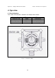
5.Technical Specifications
5.1 Electrical Specifications
A. Operating Voltage: 18-32 VDC
B.
Power Consumption
:
Max. 25mA in Stand-by
Max. 50mA in Alarm
C. Electric input protection: The input circuit is protected against voltage-
reversed polarity, voltage transients, surges and spikes according to
MIL-STD-1275A.
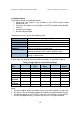
D. Electrical outputs
•
Dry Contact Relays
:
Table 13: Contact Ratings
Relay
Name
Type Normal
position
Maximum Ratings
Alarm SPST N.O. 2A at 30VDC or 0.5A at 250 VAC
Fault * SPST N.C. 2A at 30VDC or 0.5A at 250 VAC
• The FAULT relay will normally be energized and the contact will be closed during
normal operation of the detector. The contact will be open at Fault condition or low
voltage.
• The relay outputs are not available in the intrinsically safe model 20/20MI-XX-X-C.
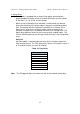
• 4-20mA Current Output:
The 4-20mA is isolated sink option.
The maximum permitted load resistor is 600Ohm.
STATE Output
FAULT 0 + 0.5mA
BIT FAULT 2mA±10%
NORMAL 5mA±10%
WARNING 10mA±5%
ALARM 15mA±5%
•
Communication Network:
The detector is equipped with an RS-485 communication link that can be
used in installations with computerized controllers. The communications
protocol is Modbus compatible.
This protocol is a standard and widely used.
It enables continuous communication between a single standard
Modbus controller (Master device) and a serial Network of up to 247
detectors.
It enables connection between different types of Spectrex detectors or
other Modbus devices to the same Network.